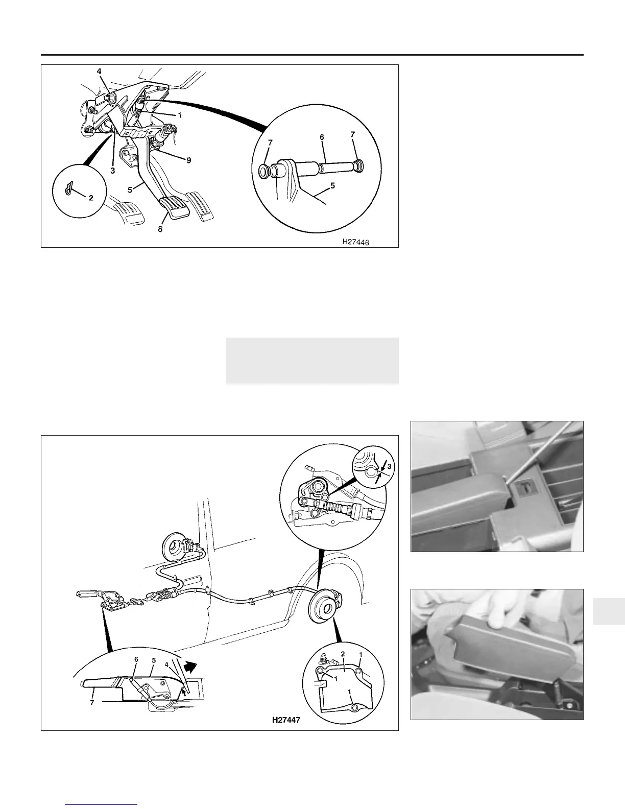
2 Disconnect the return spring from the brake
pedal and pedal bracket (see illustration).
3 Extract the retaining spring clip and
withdraw the clevis pin securing the brake
servo pushrod to the pedal.
4 Undo the nut, remove the washer and
withdraw the brake pedal pivot bolt from the
pedal bracket. Remove the pedal from the
car.
5 Prise out the two pedal bushes and
withdraw the spacer tube.
6 Check the condition of the components,
and renew as necessary.
Refitting
7 Refitting is a reversal of removal.
17 Handbrake - adjustment
2
1 Due to the self-adjusting action of the rear
brakes, adjustment of the handbrake should
normally only be necessary after removal and
refitting of any of the handbrake components.
2 To check the adjustment, chock the front
wheels, remove the rear wheel trim and
slacken the roadwheel nuts. Jack up the rear
of the car and support it on axle stands.
Remove both rear roadwheels and release the
handbrake.
3 On early models, undo the three bolts each
side securing the handbrake linkage covers to
the rear brake calipers, and remove the
covers.
4 Check the clearance between the
handbrake linkage lever and the stop-pin on
both calipers (see illustration). If the
clearance on either side is outside the
tolerance given in the Specifications, adjust
the handbrake using the following procedure.
If the clearance is satisfactory, proceed to
paragraph 9.
5 On later models it will be necessary to
remove the centre console, as described in
Chapter 11, for access to the handbrake
adjuster. On early models it is only necessary
to remove the handbrake lever trim cover as
follows. From inside the car, carefully prise
out the coin holders or switch panels on each
side of the centre console, then raise the lid
on the cassette holder at the rear of the
console.
6 Using a screwdriver as a lever, carefully
prise up the rear of the handbrake lever trim
cover, and remove the cover from the lever
(see illustrations).
7 Turn the handbrake adjuster on the side of
the handbrake lever to increase or decrease
the previously-measured clearance, as
Braking system 9•13
17.6a Prise up the rear of the handbrake
lever trim cover . . .
17.6b . . . and remove the cover from the
lever
17.4 Handbrake adjustment details
9
1380 Rover 800 Series Remake
1 Handbrake linkage cover retaining
bolts
2 Handbrake linkage cover
3 Handbrake linkage lever-to-stop-pin
clearance measuring point
4 Using a lever to prise up the
handbrake lever trim cover
(where applicable)
5 Handbrake lever trim cover
6 Handbrake adjuster
7 Handbrake lever
16.2 Brake pedal mounting details
1 Return spring
2 Clevis pin spring clip
3 Clevis pin
4 Pedal pivot bolt
5 Brake pedal
6 Spacer tube
7 Pedal bushes
8 Pedal pad
9 Stop-light switch


 To Next Page
 Loading...
