side of the lever, and remove the adjuster and
spacing washer from the front cable.
9 Release the front cable and gaiter from the
handbrake lever assembly, then remove the
cable from the gaiter.
Refitting
10 Refitting is a reversal of removal. Adjust
the handbrake as described in Section 17
before lowering the car to the ground.
20 Handbrake cable (rear) -
removal and refitting
2
Removal
1 Chock the front wheels, remove the rear
wheel trim and slacken the wheel nuts. Jack
up the rear of the car and support it on axle
stands. Remove the rear roadwheels and
release the handbrake.
2 Release the exhaust system rubber
mountings, lower the system at the rear, and
support it on blocks to avoid straining the
front flexible joint.
3 Undo the retaining bolts and remove the
front and rear exhaust system heat shields
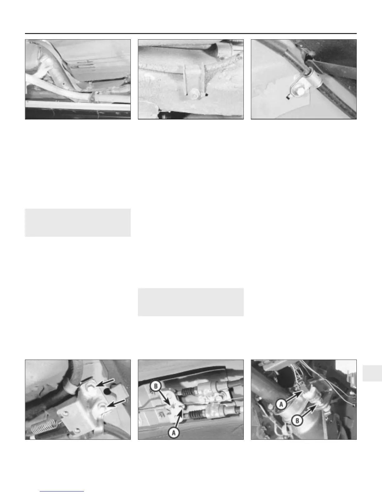
(see illustration).
4 On early models, undo the three bolts and
remove the handbrake linkage cover from the
brake caliper.
5 Extract the spring clip and withdraw the
clevis pin securing the handbrake cable to the
linkage lever on the caliper (see illus-
tration 8.5).
6 Withdraw the spring clip securing the cable
to the abutment bracket, and remove the
cable from the caliper.
7 Undo the bolts and release the cable
support clips on the suspension arm, chassis
member and underbody (see illustrations).
8 Disconnect the return spring, extract the
spring clip and withdraw the clevis pin
securing the front handbrake cable to the
compensator (see illustration).
9 Turn the rear cable end through 90º, and
release it from the slot in the compensator.
10 Withdraw the cable from the abutment
bracket, and remove it from under the car.
Remove the support clips from the cable.
Refitting
11 Refitting is a reversal of removal. Adjust
the handbrake as described in Section 17
before lowering the car to the ground.
21 Stop-light switch - removal,
refitting and adjustment
1
Removal
1 From inside the car, release the turnbuckles
and lift out the trim panel over the clutch,
brake and accelerator pedals.
2 Disconnect the switch wiring multiplug,
then slacken the locknut and unscrew the
switch from the brake pedal bracket (see
illustration).
Refitting and adjustment
3 Refit the switch to the brake pedal bracket
then adjust its position as follows.
4 Temporarily reconnect the wiring multiplug
so that the switch terminals connected to the
green/purple, and purple or purple/pink wires
can be noted.
5 Remove the multiplug once more and
connect an ohmmeter across the switch
green/purple terminal, and purple or
purple/pink terminal.
6 Turn the switch anti-clockwise until the
ohmmeter reads zero. Now turn the switch
clockwise until the ohmmeter reads infinity.
On cars equipped with cruise control, turn
the switch clockwise one further turn. On
cars without cruise control, turn the switch
clockwise a further half a turn. Hold the
switch in this position and tighten the
locknut.
7 Disconnect the ohmmeter and reconnect
the switch wiring multiplug. Ensure that the
multiplug is correctly connected otherwise the
stop lights will illuminate whenever the ignition
is switched on.
8 Refit the trim panel over the pedals.
Braking system 9•15
20.7b . . . and rear underbody20.7a Cable support on the chassis
member . . .
20.3 Removing the rear heat shield from
the exhaust system
21.2 Stop-light switch wiring multiplug (A)
and locknut (B)
20.8 Handbrake cable return spring (A)
and retaining clevis pin (B)
20.7c Front cable support retaining bolts
(arrowed)
9
1380 Rover 800 Series Remake


 To Next Page
 Loading...
