22 Vacuum servo unit - general
information and testing
1
General information
1 A vacuum servo unit is located between the
brake pedal and master cylinder, to provide
assistance to the driver when the brake pedal
is depressed. This reduces the effort required
by the driver to operate the brakes under all
braking conditions.
2 The unit operates by vacuum obtained from
the inlet manifold, and consists basically of a
diaphragm, control valve and non-return
valve.
3 With the brake pedal released, vacuum is
channelled to both sides of the diaphragm,
but when the pedal is depressed, one side is
opened to atmosphere. The resultant unequal
pressures are harnessed to assist in
depressing the master cylinder pistons.
4 Normally, the servo unit is very reliable, but
if the unit becomes faulty it must be renewed
complete, as repair is not possible. In the
event of failure, the hydraulic system is in no
way affected, except that higher pedal
pressures will be necessary.
Testing
5 To test the servo unit, depress the brake
pedal several times with the engine switched
off, to destroy the vacuum.
6 Apply moderate pressure to the brake
pedal, then start the engine. The pedal should
move down slightly as the vacuum is restored,
if the servo is operating correctly.
7 Now switch off the engine and wait five
minutes. Vacuum should still be available for
at least one assisted operation of the pedal.
23 Vacuum servo unit - removal
and refitting
3
Removal
1 Remove the master cylinder as described in
Section 11.
2 From inside the car, release the turnbuckles
and lift out the trim panel over the clutch,
brake and accelerator pedals.
3 Extract the retaining clip and withdraw the
clevis pin securing the servo pushrod to the
brake pedal.
4 From within the engine compartment,
remove the vacuum hose elbow from the front
face of the servo by prising it out of its
grommet.
5 Unscrew the four retaining nuts inside the
car, and withdraw the servo unit from the
engine compartment bulkhead.
6 With the servo removed, the air filter can be
renewed if necessary. Withdraw the dust
cover over the air filter and pushrod. Hook out
the washer and old filter, and cut the filter to
allow removal over the pushrod fork. Similarly
cut the new filter, place it in position in the
housing, and refit the washer and dust cover.
Refitting
7 Refitting is a reversal of removal. Use a new
gasket on the servo-to-bulkhead mating face,
and tighten the retaining nuts to the specified
torque. Refit the master cylinder as described
in Section 11.
24 Anti-lock braking system -
general information
Later Rover 800 series models are available
with an anti-lock braking system (ABS) as
standard equipment or an optional extra. The
system is used in conjunction with the normal
braking system to provide greater stability,
improved steering control and shorter
stopping distances under all braking
conditions. Two different ABS systems have
been used, the later type introduced for the
1992 model year, operates in basically the
same way as the early system but
incorporates modifications to the hydraulic
modulator and electronic control unit. A brief
description of the operation of both systems
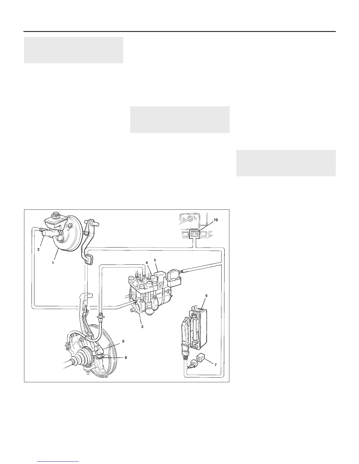
is as follows (see illustration). Each wheel is
provided with a wheel speed sensor, which
monitors the wheel rotational speed. The
sensor consists of a magnetic core and coil,
and is mounted at a predetermined distance
from a toothed reluctor ring. The reluctor rings
for the front wheels are pressed onto the
driveshaft outer constant velocity joints, and
those for the rear wheels are pressed onto the
rear hubs. When each hub turns, the magnetic
field of the sensor is altered as the reluctor
ring teeth pass the sensor head, thus inducing
an alternating voltage, the frequency of which
varies according to wheel speed.
Signals from the wheel speed sensors are
sent to an electronic control unit, which can
accurately determine whether a wheel is
accelerating or decelerating in relation to a
reference speed. Information from the
electronic control unit is sent to the hydraulic
modulator which, on the early system,
contains four solenoids each operating one
inlet and one exhaust valve for each brake. On
the later system, the modulator contains one
solenoid for each front brake, plus one
solenoid and a copy valve for the rear brakes.
On both systems the solenoids all work
independently of each other in three distinct
phases:
9•16 Braking system
24.1 Anti-lock braking system main components (pre-1992 model year version shown,
later version similar)
1 Vacuum servo unit
2 Master cylinder
3 Hydraulic modulator
4 Modulator control relay -
solenoid valve operation
5 Modulator control relay -
return pump operation
6 Electronic control unit
7 Over-voltage protection
relay
8 Front wheel speed sensor
reluctor ring
9 Front wheel speed sensor
10 ABS warning light
1380 Rover 800 Series Remake


 To Next Page
 Loading...
