Pressure build-up phase: The solenoid inlet
valves are open, and hydraulic pressure from
the master cylinder is applied directly to the
brake calipers.
Constant pressure phase: The solenoid inlet
and exhaust valves are closed, and hydraulic
pressure at the calipers is maintained at a
constant level, even though master cylinder
pressure may increase.
Pressure reduction phase: The solenoid
inlet valve is closed to prevent further
hydraulic pressure reaching the caliper and, in
addition, the exhaust valve is open, to reduce
existing pressure and release the brake. Fluid
is returned to the master cylinder in this phase
via the return pump in the hydraulic
modulator.
The braking cycle for one wheel is therefore
as follows, and will be the same for all four
wheels, although independently.
Wheel rotational speed is measured by the
wheel speed sensors, the information is
processed by the electronic control unit. By
comparing the signals received from each
wheel, the control unit can determine a
reference speed, and detect any variation
from this speed, which would indicate a
locking brake. Should a lock-up condition be
detected, the control unit initiates the
constant pressure phase, and no further
increase in hydraulic pressure is applied to the
affected brake. If the lock-up condition is still
detected, the pressure reduction phase is
initiated to allow the wheel to turn. The control
unit returns to the constant pressure phase
until the wheel rotational speed exceeds a
predetermined value, then the cycle repeats
with the control unit re-initiating the pressure
build-up phase. This control cycle is
continuously and rapidly repeated, until the
brake pedal is released or the car comes to a
stop.
Additional circuitry within the electronic
control unit monitors the functioning of the
system, and informs the driver of any fault
condition by means of a warning light. Should
a fault occur, the system switches off allowing
normal braking, without ABS, to continue.
25 Anti-lock braking system -
component removal and
refitting
3
ABS main relays
1 Disconnect the battery negative (earth) lead
(refer to Chapter 5, Section 1).
2 Undo the screw and lift off the plastic cover
over the hydraulic modulator.
3 Remove the relays by pulling them out of
their location. The relay nearest the hydraulic
pipe connection end of the modulator controls
the solenoid valve operation, and the relay
furthest away from the hydraulic pipe
connections controls the return pump
operation.
4 Refitting is the reversal of removal.
Over-voltage protection relay
5 An over-voltage protection relay is only
used on the early systems.
6 Disconnect the battery negative (earth) lead
(refer to Chapter 5, Section 1).
7 Working in the luggage compartment,
release the turnbuckle and lift off the cover
over the electronic control unit.
8 Withdraw the relay from its socket which is
located below the ECU on Saloon models,
and to the side of the ECU, behind the trim
panel on Fastback models.
9 Refitting is a reversal of removal.
Electronic control unit
Early system
10 Disconnect the battery negative (earth)
lead (refer to Chapter 5, Section 1).
11 Working in the luggage compartment on
the left-hand side, release the turnbuckle and
lift off the control unit cover.
12 Disconnect the wiring multiplug by
depressing the spring tab at the cable end, lift
the plug up at the cable end, then disengage
the tab at the other end.
13 Undo the retaining bolts and remove the
unit from its location.
14 Refitting is a reversal of removal, but
ensure that the wiring multiplug engages
securely with an audible click from the spring
tab.
Later system
15 On the system fitted to later models, the
ECU is attached to the hydraulic modulator.
16 Disconnect the battery negative (earth)
lead (refer to Chapter 5, Section 1).
17 Undo the screw and lift off the plastic
cover over the hydraulic modulator.
18 Release the metal clip securing the main
wiring harness to the ECU then disconnect
the three wiring multiplugs.
19 Undo the six Torx screws and withdraw
the ECU from the top of the hydraulic
modulator.
20 Refitting is a reversal of removal.
Hydraulic modulator
Note: Before starting work, refer to the
warning at the beginning of Section 2
concerning the dangers of hydraulic fluid.
Early system
21 Disconnect the battery negative (earth)
lead (refer to Chapter 5, Section 1).
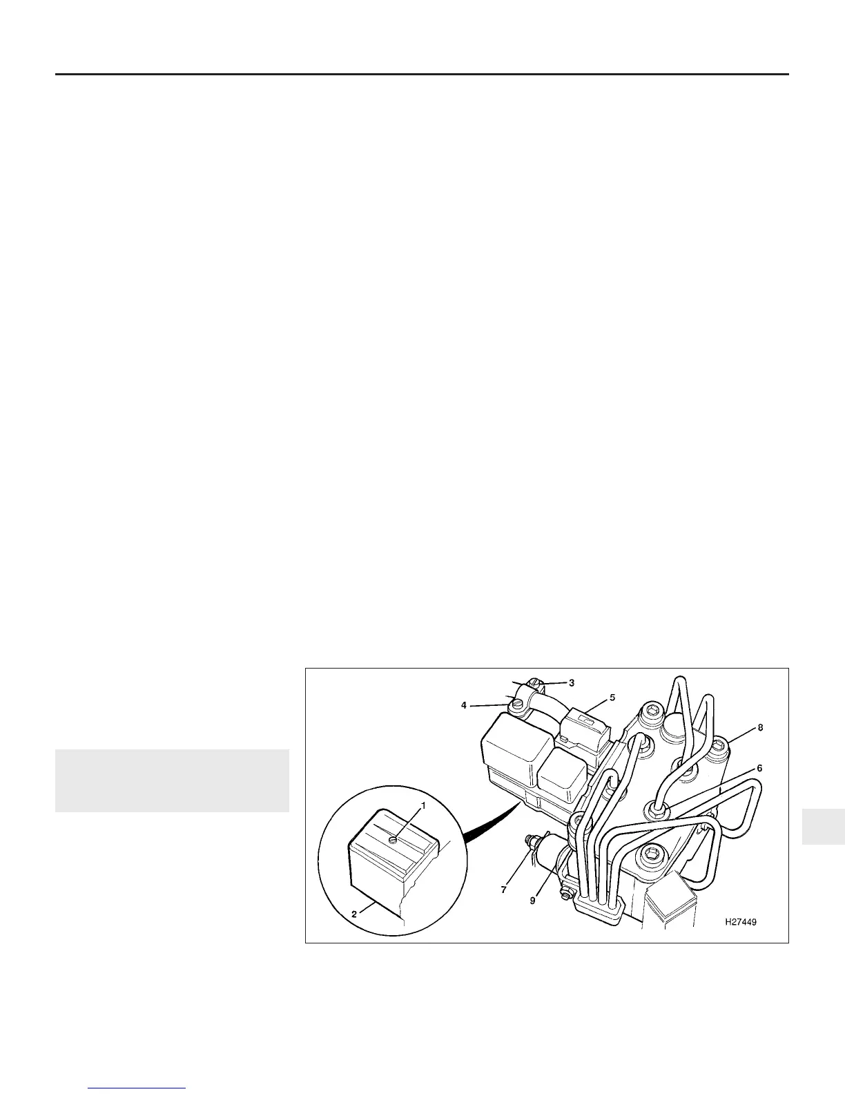
22 Undo the screw and lift off the plastic
cover over the hydraulic modulator. Unscrew
the cable clamp and disconnect the
modulator wiring multiplug. Undo the earth
terminal nut and disconnect the earth lead
from the modulator (see illustration).
23 Remove the master cylinder reservoir filler
cap, and place a piece of polythene over the
filler neck. Seal the polythene with an elastic
band, ensuring that an airtight seal is
obtained. This will minimise brake fluid loss
during subsequent operations. Place rags
beneath the modulator as an added
precaution against fluid spillage.
24 If no identification labels are present on
the modulator brake pipe unions, identify
each pipe and its location as an aid to
refitting. The modulator ports should be
stamped on the modulator body with a two-
letter code as follows:
VR Right-hand front
VL Left-hand front
HR Right-hand rear
HL Left-hand rear
25 Unscrew each brake pipe union at the
modulator, withdraw the pipe, and
immediately plug the pipe end and orifice.
Release the pipe support bracket from the
side of the modulator, and carefully ease the
pipes clear.
Braking system 9•17
25.22 ABS hydraulic modulator attachments (early version shown)
1 Cover retaining screw
2 Modulator relay cover
3 Cable clamp screws
4 Cable clamp
5 Multiplug
6 Brake pipe unions
7 Mounting nuts
8 Modulator
9 Mounting rubbers
9
1380 Rover 800 Series Remake


 To Next Page
 Loading...
