26 Slacken the modulator mounting nuts and
remove the unit from its location. Do not
attempt to dismantle the modulator, as it is a
sealed unit, and no repairs are possible.
27 Refitting is a reversal of removal. Bleed
the hydraulic system as described in Sec-
tion 2 on completion.
Later system
28 Disconnect the battery negative (earth)
lead (refer to Chapter 5, Section 1).
29 Remove the electronic control unit from
the modulator as described previously.
30 Undo the earth terminal nut and
disconnect the earth lead from the modulator.
31 Remove the master cylinder reservoir filler
cap, and place a piece of polythene over the
filler neck. Seal the polythene with an elastic
band, ensuring that an airtight seal is
obtained. This will minimise brake fluid loss
during subsequent operations. Place rags
beneath the modulator as an added
precaution against fluid spillage.
32 If no identification labels are present on
the modulator brake pipe unions, identify
each pipe and its location as an aid to
refitting. The modulator ports should be
stamped on the modulator body with a two-
letter code as follows:
RF Right-hand front
LF Left-hand front
RR Right-hand rear
LR Left-hand rear
33 Unscrew each brake pipe union at the
modulator, withdraw the pipe, and
immediately plug the pipe end and orifice.
34 Slacken the three modulator mounting
nuts and remove the unit from its location. Do
not attempt to dismantle the modulator, as it
is a sealed unit, and no repairs are possible.
35 Refitting is a reversal of removal. Bleed
the hydraulic system as described in Sec-
tion 2 on completion.
Front wheel speed sensor
36 Apply the handbrake, remove the front
wheel trim and slacken the wheel nuts. Jack
up the front of the car and support it on axle
stands. Remove the front roadwheel.
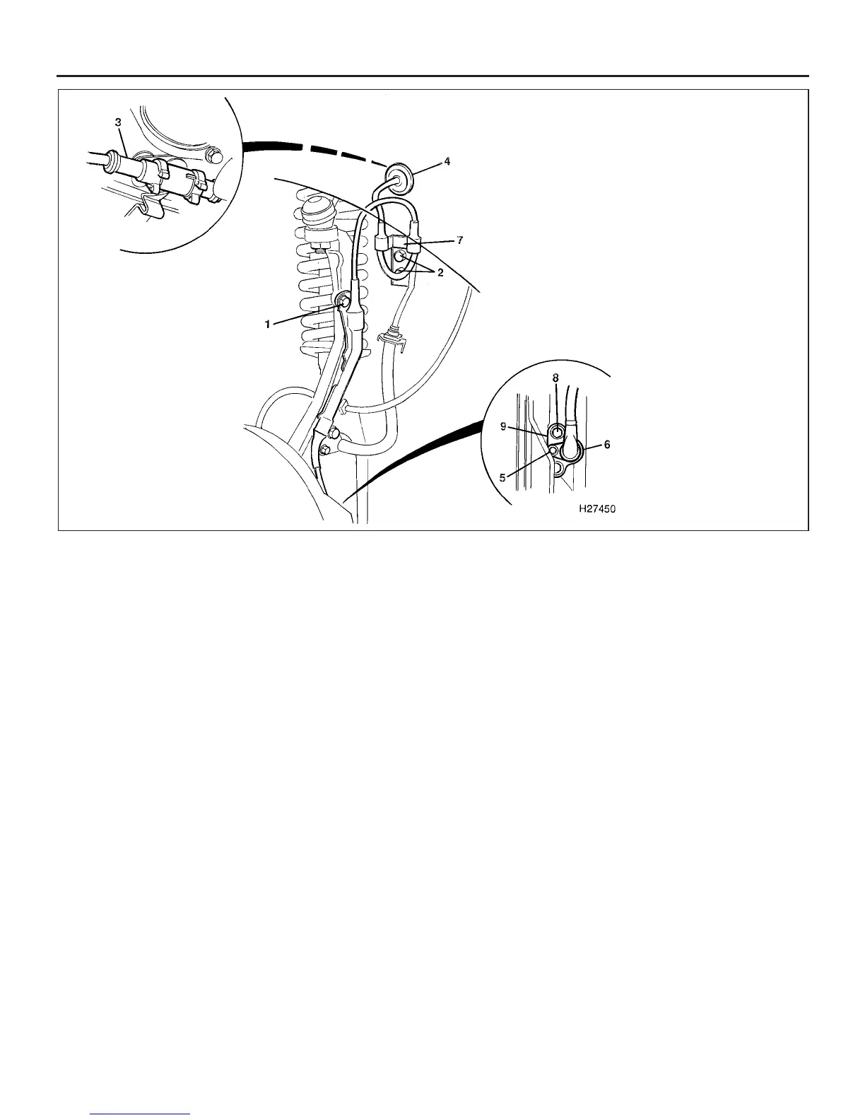
37 Undo the bolts securing the cable harness
support brackets to the steering knuckle and
inner wheelarch panel (see illustration).
38 From within the engine compartment,
release the wiring connector from its holder,
and separate the connector. Release the
wheelarch grommet and pull the wiring
through to the wheelarch.
39 Undo the bolt securing the sensor to the
sensor bracket on the steering knuckle, and
carefully prise the sensor out of the bracket.
40 Release the sensor wiring from the
support bracket, and remove the unit from the
car.
41 Undo the two bolts and remove the
sensor bracket from the steering knuckle.
42 Prior to refitting, clean the sensor, sensor
bracket and the mounting area on the steering
knuckle, removing all traces of dirt and grit.
43 Refitting is a reversal of removal.
Lubricate the sensor and sensor bracket with
Rocol J166 or Molykote FB180, and ensure
that the bracket bosses face the hub when
fitting. Tighten all bolts to the specified
torque, and check the sensor-to-reluctor ring
clearance, which should be as given in the
Specifications.
Rear wheel speed sensor
44 Chock the front wheels, remove the rear
wheel trim and slacken the wheel nuts. Jack
up the rear of the car and support it on axle
stands. Remove the rear roadwheel.
45 Working in the luggage compartment on
the left-hand side, release the turnbuckle and
lift off the cover over the electronic control
unit (early systems only) (see illustration).
46 Remove the left-hand side inner trim
panel.
47 Disconnect the wheel speed sensor wiring
at the cable connector.
48 Undo the two screws and remove the
plastic liner on the front face of the rear
wheelarch.
49 Release the grommets in the luggage
compartment floor and inner wheelarch, then
pull the wiring through to the wheelarch.
50 Undo the two bolts and remove the cable
cover and guide from the chassis member.
51 Release the cable ties and retaining clips
9•18 Braking system
25.37 Front wheel speed sensor attachments
1380 Rover 800 Series Remake
1 Cable harness support bracket
bolt on steering knuckle
2 Cable harness support bracket
and bolt on inner wheelarch
panel
3 Wiring connector
4 Wheelarch grommet
5 Sensor-to-sensor bracket
retaining bolt
6 Sensor
7 Harness support bracket
8 Sensor bracket-to-steering
knuckle retaining bolt
9 Sensor bracket


 To Next Page
 Loading...
