1 General information
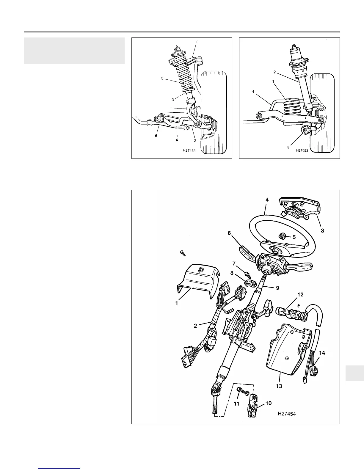
The independent front suspension is by
unequal length upper and lower suspension
arms, and utilizes coil springs and telescopic
shock absorbers (see illustration). Each spring
and shock absorber assembly is attached to the
body turret at its upper end by a rubber-
cushioned mounting, and to the lower
suspension arm by a forged, forked-shaped
member. Fore and aft location of each
suspension assembly is by a tie-bar, and an anti-
roll bar is used to minimise body roll. The front
steering knuckles, which carry the hub bearings,
brake calipers and the hub/disc assemblies,
pivot on balljoints - one incorporated in the upper
suspension arm, and one secured to the lower
part of the steering knuckle itself.
The independent rear suspension is by
transverse and trailing links with coil springs,
telescopic shock absorbers, and an anti-roll
bar (see illustration). The shock absorbers are
attached to the body at their upper ends by
rubber-cushioned mountings, and clamped to
the hub carriers at their lower ends. Lateral
location of each suspension assembly is
provided by the transverse link, which also
provides the lower location of the coil spring.
Fore and aft location of each suspension
assembly is controlled by the trailing link,
which is attached to the hub carrier by means
of a bracket incorporating an eccentric
mounting bolt for rear wheel toe adjustment.
Self-levelling rear suspension, which reacts
to vehicle loading and automatically maintains
the normal trim heights, is available on certain
models. The self-levelling units are sealed
dampers fitted in place of the normal rear
shock absorbers. A pump in the damper
operates under the action of the suspension
to raise the rear of the car until normal trim
height is regained. On an undulating road, this
process will be carried out within one mile.
When the additional load is removed, the
suspension remains at the correct level.
Power-assisted rack and pinion steering
gear is standard equipment on all models.
Movement of the steering wheel is transmitted
to the steering gear by a steering column
shaft containing two universal joints (see
illustration). These allow for provision of a
rake-adjustable column assembly, and also
allow the necessary upward deflection of the
column, for driver safety, in the event of front
end impact. The front wheels are connected
to the steering gear by track rods, each
having an inner and outer balljoint. On early
4-cylinder engine models, hydraulic fluid
pressure for the power assistance is provided
by a pump, mounted on the left-hand end of
the engine and belt-driven from a pulley on
the inlet camshaft. On later 4-cylinder, and all
V6 engine models, the pump is mounted at
the timing belt end of the engine and is belt-
driven from the crankshaft pulley.
Suspension and steering systems 10•3
1.2 Rear suspension assembly
1 Coil spring 3 Trailing link
2 Shock absorber 4 Anti-roll bar
1.1 Front suspension assembly
1 Upper suspension arm 4 Tie-bar
2 Lower suspension arm 5 Coil spring
3 Shock absorber 6 Anti-roll bar
1.4 Exploded view of the steering column components
10
1380 Rover 800 Series Remake
1 Column upper shroud
2 Wiring harness
3 Steering wheel pad
4 Steering wheel
5 Steering wheel nut
6 Multifunction switches
7 Shear bolts
8 Lock saddle
9 Column shaft
10 Universal joint
11 Clamp bolt
12 Column
lock/ignition
switch
13 Column lower
shroud
14 Wiring
harness


 To Next Page
 Loading...
