2 Front steering knuckle
assembly -
removal and refitting
3
Note: A new driveshaft retaining nut will be
required for refitting.
Removal
1 While the car is standing on its wheels.
firmly apply the handbrake and put the
transmission in gear (PARK on automatic
models).
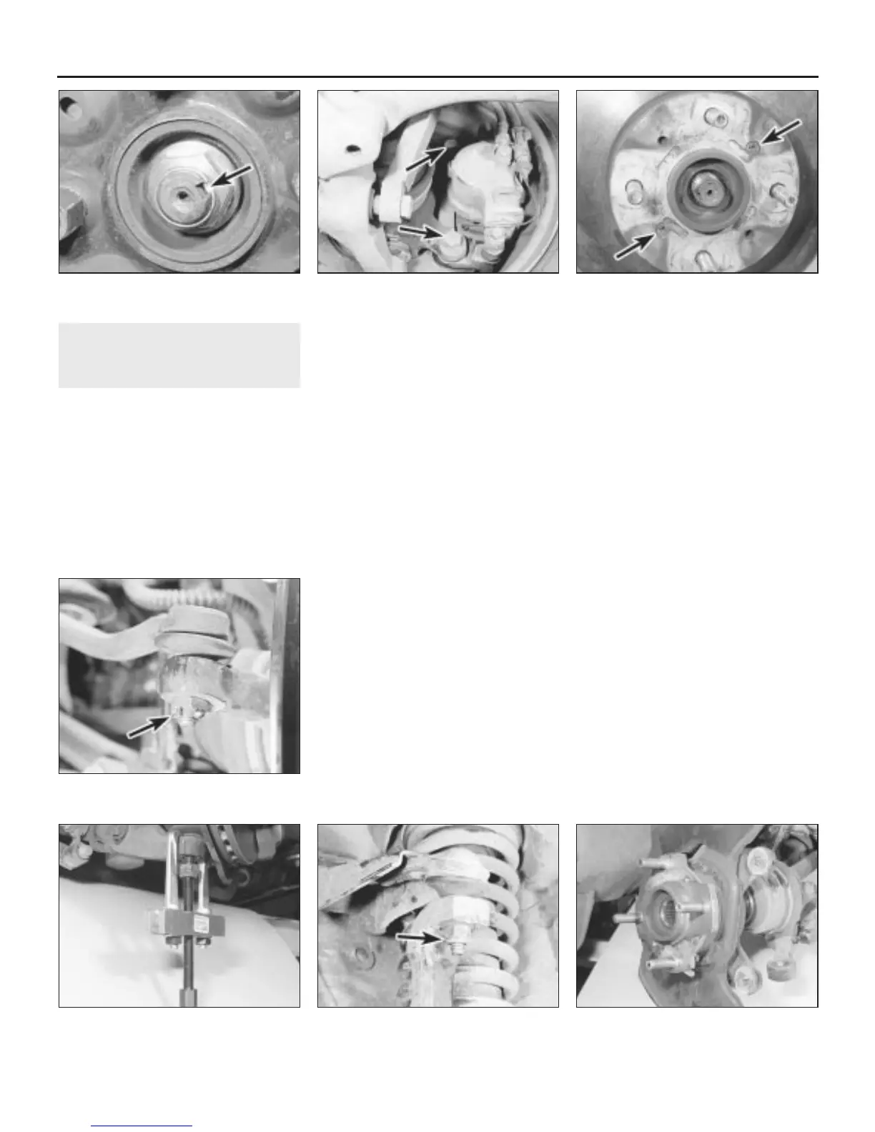
2 Remove the wheel trim, and using a small
punch, knock up the staking that secures the
driveshaft retaining nut to the groove in the
constant velocity joint stub shaft (see
illustration). Note that a new retaining nut will
be needed for reassembly.
3 Using a socket, sturdy T-bar and long
extension tube for leverage, slacken the
retaining nut half a turn. Note that the
retaining nut is tightened to a very high torque
setting, and considerable effort will be
required to slacken it.
4 Slacken the wheel nuts, jack up the front of
the car and support it on stands. Remove the
roadwheel and put the transmission in neutral.
5 Remove the driveshaft retaining nut.
6 Undo the two bolts securing the brake
caliper carrier bracket to the steering knuckle,
and the two bolts securing the brake hose
bracket to the knuckle (see illustration).
7 Withdraw the caliper and carrier bracket
assembly, complete with brake pads, off the
disc, and tie it up using string or wire from a
convenient place under the wheelarch. Take
care to avoid straining the brake hose.
8 Undo the two retaining screws and remove
the disc from the hub flange (see illustration).
9 On cars with ABS brakes, remove the front
wheel speed sensor and wiring harness from
the steering knuckle, as described in Chap-
ter 9.
10 Extract the split pin and unscrew the nut
securing the steering track rod balljoint to the
steering knuckle arm (see illustration).
Release the balljoint from the arm using a
universal balljoint separator tool.
11 Undo the nut securing the steering
knuckle balljoint to the lower suspension arm.
Release the balljoint from the arm using a
separator tool or two-legged puller (see
illustration).
12 Undo the nut securing the upper
suspension arm balljoint to the steering
knuckle, and release the balljoint using the
same procedure as for the lower balljoint (see
illustration).
13 Disengage the balljoint shanks, then
withdraw the steering knuckle from the
driveshaft (see illustration). If necessary, tap
the end of the driveshaft with a copper or
plastic mallet to release it from the hub
splines. Remove the steering knuckle
assembly from the car.
Refitting
14 Refitting the steering knuckle is a reversal
of removal, bearing in mind the following
points:
(a) Tighten all retaining nuts and bolts to the
specified torque and use a new split pin
to secure the steering track rod balljoint
nut.
(b) Use a new driveshaft retaining nut but do
not attempt to tighten this nut fully until
the weight of the car is on the roadwheels
(see illustration). Peen the nut into the
driveshaft groove using a small punch
after tightening. If a torque wrench
capable of recording the high figure
required for tightening is not available, it is
recommended that the old nut is fitted,
tightened as securely as possible, then
10•4 Suspension and steering systems
2.13 Withdrawing the steering knuckle
from the driveshaft
2.12 Undo the upper suspension arm
balljoint nut (arrowed)
2.11 Using a two-legged puller to release
the steering knuckle balljoint
2.10 Extract the track rod balljoint nut split
pin (arrowed)
2.8 Brake disc retaining screws (arrowed)2.6 Brake caliper carrier bracket securing
bolts (arrowed)
2.2 Knock up the staking (arrowed)
securing the driveshaft retaining nut
1380 Rover 800 Series Remake


 To Next Page
 Loading...
