2 Undo the nut securing the steering knuckle
balljoint to the lower suspension arm (see
illustration). Release the balljoint using a
separator tool or two-legged puller.
3 Undo the nut and remove the through-bolt
securing the shock absorber forked member
to the arm.
4 Undo the bolt securing the anti-roll bar
connecting link to the arm.
5 Undo the two bolts securing the tie-bar to
the arm.
6 Undo the nut and remove the suspension
arm inner mounting bolt (see illustration).
7 Withdraw the suspension arm from its inner
mounting location, and remove it from under
the wheelarch.
8 Check the condition of the two suspension
arm bushes, and renew these if worn or
damaged. To do this, a press will be required,
together with mandrels and distance tubes. If
this equipment is not available, have this work
done by a Rover dealer or suitably-equipped
garage.
Refitting
9 Refitting is a reversal of removal, but tighten
all nuts and bolts to the specified torque. Do
not fully tighten the inner mounting bolt or the
forked member retaining bolt until the weight
of the car is on its roadwheels.
9 Front anti-roll bar -
removal and refitting
3
Removal
1 Apply the handbrake, prise off the front
wheel trims and slacken the wheel nuts. Jack
up the front of the car and support it on axle
stands. Remove the front roadwheels.
2 Undo the single bolt each side securing the
anti-roll bar connecting links to the lower
suspension arms (see illustration).
3 Undo the two bolts each side securing the
anti-roll bar mounting brackets to the chassis
members, and remove the bar from under the
car (see illustration).
4 If required, the connecting links can be
removed after undoing the retaining nut and
bolt on each side.
5 Check the condition of the connecting link
bushes and the anti-roll bar mounting bushes,
and renew any that show signs of deterioration.
The connecting link bushes come complete
with new connecting links, and the mounting
bushes are slit along their length to allow
removal and refitting over the bar.
Refitting
6 Refitting is a reversal of removal. Tighten the
mounting and connecting link bushes to the
specified torque only with the weight of the car
on its roadwheels.
10 Front tie-bar -
removal and refitting
4
Note: On some models, it may be found that
the tie-bar-to-lower suspension arm bolts
cannot be withdrawn because of the proximity
of the driveshaft. In this case, it will be
necessary to release the lower suspension
arm balljoint and disconnect the arm from the
shock absorber, as described in Section 8.
Removal
1 Apply the handbrake, prise off the front
wheel trim and slacken the wheel nuts. Jack
up the front of the car and support it on axle
stands. Remove the front roadwheel.
2 Undo the five bolts and remove the undertray
for access to the tie-bar front mounting.
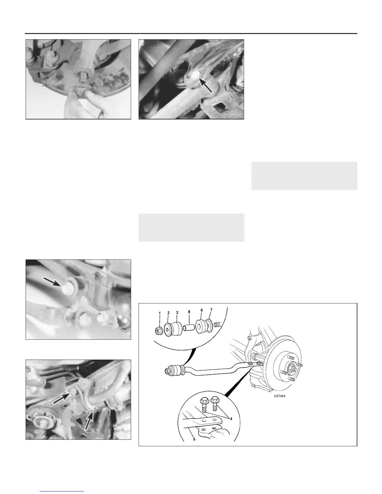
3 Undo the front mounting nut and remove
the tie-bar washer and outer mounting bush
(see illustration).
10•8 Suspension and steering systems
10.3 Front tie-bar attachment details
9.3 Anti-roll bar mounting bracket bolts
(arrowed)
9.2 Anti-roll bar connecting link bolt
(arrowed)
8.6 Lower suspension arm inner mounting
bolt (arrowed)
8.2 Undo the nut securing the steering
knuckle balljoint to the lower suspension
arm
1380 Rover 800 Series Remake
1 Front mounting
nut
2 Washer
3 Outer mounting
bush
4 Tie-bar-to-lower
suspension arm
bolts
5 Tie-bar
6 Inner mounting
bush
7 Washer
8 Spacer


 To Next Page
 Loading...
