airbag supplementary restraint system,
remove the rotary coupler as described in
Chapter 10.
14 Slacken the retaining screw in the front
centre of the switch assembly.
15 Disconnect the four wiring multiplugs at
the rear, then withdraw the switch assembly
from the steering column.
16 Undo the two screws securing the
individual switch to the main assembly.
17 Disconnect the wiring multiplug at the rear
and withdraw the switch from the main
assembly. Use a thin flat blade to release the
switch from its location as it is withdrawn.
18 The switch on the other side of the
column is removed in the same way.
19 Refitting is a reversal of removal. Refer to
Chapter 10 when refitting the rotary coupler
and steering wheel.
Centre console switches
20 Carefully prise up the coin holder or
switch panel as applicable from the side of
the centre console.
21 If individual switches are fitted, disconnect
the wiring multiplug, depress the lugs on the
side of the switch and withdraw the switch from
the coin holder panel (see illustration).
22 If a multi-switch pack is fitted, disconnect
the wiring multiplug and remove the switch
panel complete.
23 Refitting is a reversal of removal.
Door switches
24 Remove the front or rear door inner trim
panel as described in Chapter 11.
25 Release the switch pack assemblies from
the rear of the trim panel and withdraw them.
Note that the individual switches in the switch
packs cannot be removed separately. If any are
faulty, or if renewal of a switch is necessary, the
complete switch pack must be obtained.
26 Refitting is a reversal of removal.
Courtesy light door pillar
switches
27 Undo the retaining screw and withdraw the
switch from the door pillar (see illustration).
28 Disconnect the wiring and remove the
switch. Tie the wiring to the door striker plate
while the switch is removed to prevent the
wires dropping into the pillar.
29 Refitting is a reversal of removal.
Instrument cowl switch units
30 Carefully prise out the rear of the cover
plate at the extreme left-hand side of the cowl
and push the plate forward to release the front
clips (see illustration). Undo the screw
behind the plate, now exposed.
Body electrical system 12•5
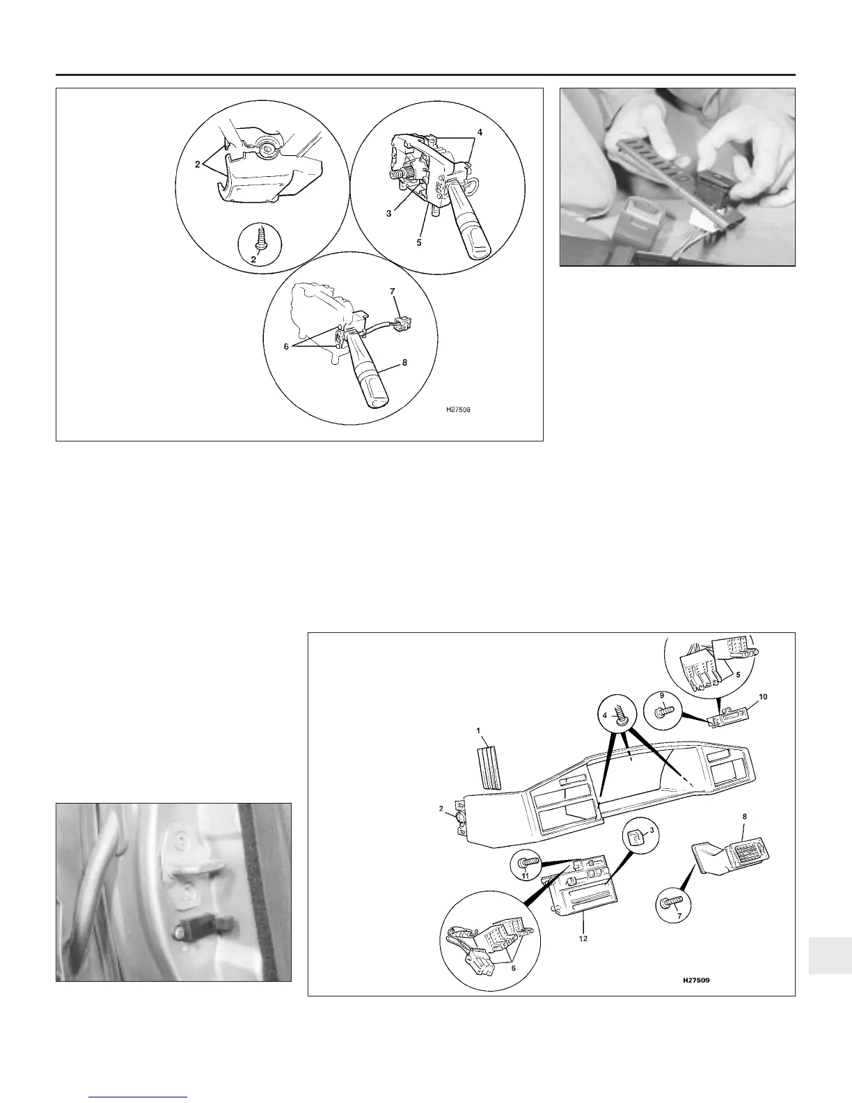
4.21 Centre console switch removal
4.10 Steering column switch details on later models
4.30 Exploded view of the instrument cowl switch units
4.27 Courtesy light door pillar switch
location
12
1380 Rover 800 Series Remake
2 Shroud retaining screws
and lower shroud
3 Switch assembly centre
retaining screw
4 Wiring multiplugs
5 Switch assembly
6 Individual switch retaining
screws
7 Wiring multiplug
8 Column switch
1 Cover plate
2 Retaining screw
3 Heater control knobs
4 Retaining screw locations
5 Switch panel multiplugs and
bulbholders
6 Heater/air conditioning
control multiplugs
and bulbholders
7 Vent panel retaining
screws
8 Vent panel
9 Switch unit
retaining screws
10 Switch unit
11 Heater/air conditioning
control unit retaining screws
12 Heater/air conditioning
control unit


 To Next Page
 Loading...
