illumination and warning light bulbs are
renewed complete with their holders.
3 If a faulty bulb is not accessible, undo the
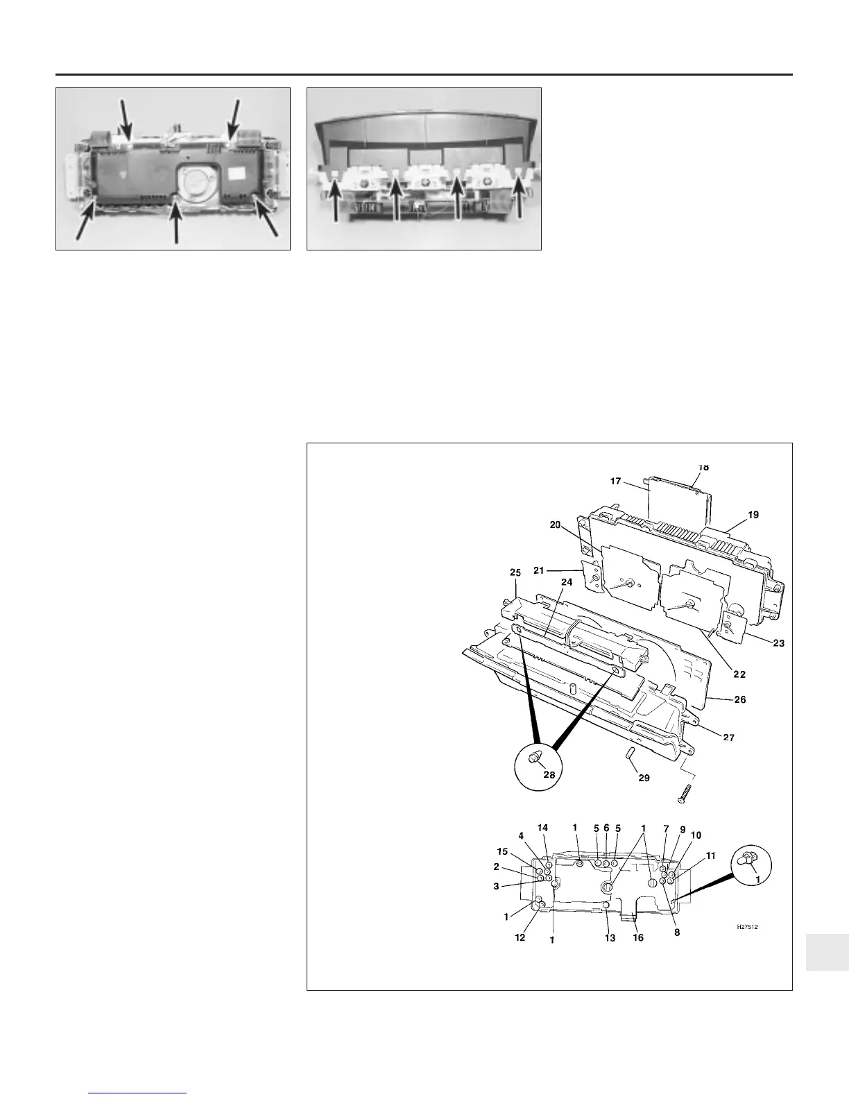
five screws securing the ECU to the rear of
the panel, and carefully lift the ECU upwards
(see illustration). Take care not to strain the
ribbon connectors. The remaining bulbs are
now accessible.
4 Refit the bulbholders by turning clockwise
to lock. Where applicable, lay the ECU in
position and secure with the five screws.
Instrument panel window and
faceplate
5 Carefully release the eight clips, four at the
top and four at the bottom, securing the
window to the instrument panel body (see
illustration).
6 Withdraw the window and remove the
faceplate.
7 Refitting is a reversal of removal.
Electronic control unit (ECU)
8 Disconnect the two ribbon connector
multiplugs and the centre wiring multiplug
from the top of the ECU.
9 Undo the five screws and withdraw the
ECU from the rear of the instrument panel.
10 Refitting is a reversal of removal.
Secondary printed circuit
11 Remove the ECU as described previously.
12 Undo the two voltmeter retaining nuts.
13 Remove the bulbholders as applicable.
14 Undo the five printed circuit retaining
screws.
15 Release the five retaining studs.
16 Ease the printed circuit off the two
locating pins, and remove it from the rear of
the panel.
17 Refitting is a reversal of removal.
Main printed circuit
18 Remove the instrument panel window and
faceplate, the ECU and the secondary printed
circuit as described previously
19 Withdraw the warning light colour strips
from the front of the panel.
20 Pull off the trip reset button.
21 Disconnect the ribbon connector from the
tachometer by carefully levering off the metal
retainer with a small screwdriver. Remove the
metal retainer from the ribbon.
22 Remove the bulbholders.
23 Undo the nuts from the gauge studs.
24 Release the two printed circuit retaining
studs.
25 Ease the printed circuit off the locating
pins, and remove it from the rear of the panel.
26 Refitting is a reversal of removal.
Speedometer
27 Remove the instrument panel window and
faceplate, and the ECU as described
previously.
28 Undo the three speedometer retaining
screws, release the wiring harness and
remove the speedometer from the instrument
panel.
29 Refitting is a reversal of removal.
Tachometer
30 Remove the instrument panel window and
faceplate, and the ECU as described previously.
31 Undo the two tachometer retaining
screws.
32 Disconnect the ribbon connector from the
tachometer by carefully levering off the metal
retainer with a small screwdriver. Remove the
metal retainer from the ribbon.
33 Remove the tachometer from the
instrument panel.
34 Refitting is a reversal of removal.
Voltmeter, oil pressure, coolant
temperature and fuel gauges
35 Remove the instrument panel window and
faceplate, and the ECU as described
previously.
36 Undo the two retaining nuts and remove
the relevant gauge as applicable.
Body electrical system 12•11
10.5 Instrument panel window upper
retaining clips (arrowed)
10.3 Instrument panel ECU retaining
screws (arrowed)
10.39 Exploded view of the instrument panel fitted to later models
12
1380 Rover 800 Series Remake
1 Panel rear illumination bulbs
2 Fuel system check warning light
bulb (where fitted)
3 Ignition warning light bulb
4 Cruise control warning light bulb
(where fitted)
5 Direction indicator warning light
bulb
6 Main beam warning light bulb
7 Trailer direction indicator
warning light bulb
8 Low oil pressure warning
light bulb
9 Sidelight warning light
bulb
10 Hazard warning light
bulb
11 Brake warning light bulb
12 Low fuel warning light bulb
13 Transmission S4 switch warning
light bulb (where fitted)
14 Catalyst overheat warning light
bulb (where fitted)
15 ABS warning light bulb (where
fitted)
16 Printed circuit
17 Circuit board
18 Circuit board cover
19 Instrument panel housing
20 Tachometer
21 Temperature gauge
22 Speedometer
23 Fuel gauge
24 Illumination bulb circuit board
25 Panel illumination covers
26 Faceplate
27 Cowl and window
28 Panel front illumination bulbs
29 Trip reset button


 To Next Page
 Loading...
