37 Refitting is a reversal of removal.
Later models
38 Remove the instrument panel from the car
as described in Section 9.
Panel illumination and warning light
bulbs
39 The bulbholders are secured to the front
rear of the instrument panel by a bayonet
fitting, and are removed by turning the holders
anti-clockwise (see illustration). Note that the
illumination and warning light bulbs are
renewed complete with their holders.
40 If a faulty bulb is not accessible, undo the
three screws securing the circuit board and its
cover to the rear of the panel. Remove the
cover and carefully lift the circuit board
upwards. Take care not to strain the ribbon
connectors. The remaining bulbs are now
accessible.
41 Refit the bulbholders by turning clockwise
to lock. Where applicable, lay the circuit board
in position and secure with the cover and
retaining screws.
Instrument panel window and
faceplate
42 Carefully release the eight clips, four at
the top and four at the bottom, securing the
window to the instrument panel body.
43 Undo the four screws, two at each end of
the instrument panel.
44 Withdraw the window and release the
additional bulbholder at the rear.
45 Pull off the trip reset button and remove
the faceplate.
46 Refitting is a reversal of removal.
Circuit board
47 Disconnect the ribbon connector
multiplug from the circuit board.
48 Undo the three screws and withdraw the
cover and circuit board from the rear of the
instrument panel.
49 Refitting is a reversal of removal.
Tachometer
50 Remove the instrument panel window and
faceplate, and the circuit board as described
previously.
51 Undo the three tachometer retaining
screws and withdraw the tachometer from the
instrument panel.
52 Refitting is a reversal of removal.
Speedometer
53 Remove the instrument panel window and
faceplate, and the circuit board as described
previously.
54 Undo the four small screws, and three
large screws at the rear of the speedometer
and withdraw it from the instrument panel.
55 Refitting is a reversal of removal.
Coolant temperature and fuel gauges
56 Remove the instrument panel window and
faceplate and, if the temperature gauge is
being removed, the circuit board, as
described previously.
57 Undo the three gauge retaining screws
and remove the relevant gauge from the
instrument panel.
58 Refitting is a reversal of removal.
Printed circuit
59 Remove all the components from the
instrument panel as described previously.
60 Release the printed circuit from the thirty
retaining pins and remove it carefully from the
instrument panel.
61 Refitting is a reversal of removal.
11 Central control unit -
description, removal and
refitting
1
Description
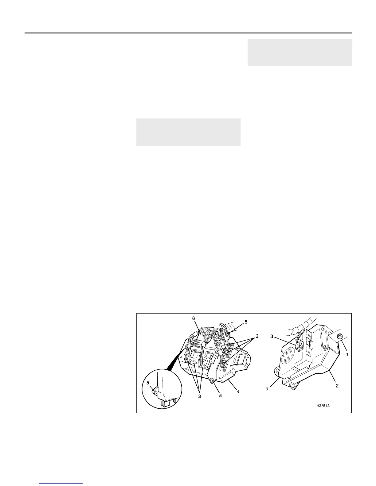
1 Later models are equipped with a central
control unit (CCU) located under the facia
behind the fusebox (see illustration). The
function of the unit is to replace the various
control units located behind the relay tower
on earlier models, and to reduce the
complexity of the wiring harness previously
required.
2 The CCU incorporates a diagnostic feature
for connection to a Rover dedicated test
appliance.
Removal
3 Disconnect the battery negative (earth) lead
(refer to Chapter 5, Section 1).
4 Detach the access panel or fusebox cover
below the steering column.
5 Undo the retaining nut then withdraw the
unit from the mounting pin.
6 Disconnect the wiring multiplugs at the rear
of the unit and remove the unit from the car.
Refitting
7 Refitting is a reversal of removal.
12 Clock -
removal and refitting
1
Digital clock - early models
Removal
1 Disconnect the battery negative (earth) lead
(refer to Chapter 5, Section 1).
2 Undo the two screws at the base of the
oddment tray opening.
3 Withdraw the oddment tray and disconnect
the clock wiring multiplug.
4 Remove the oddment tray. Undo the two
clock retaining screws and remove the clock.
Refitting
5 Refitting is a reversal of removal.
Digital clock - later models
Removal
6 Disconnect the battery negative (earth) lead
(refer to Chapter 5, Section 1).
7 Carefully prise the clock assembly from the
lower facia. The unit is retained by moulded
clips which compress as the unit is
withdrawn.
8 Disconnect the multiplug and remove the
clock from the lower facia.
9 To renew the illumination bulb, turn the
bulbholder anti-clockwise to remove.
Refitting
10 Refitting is a reversal of removal.
Analogue clock
Removal
11 Disconnect the battery negative (earth)
lead (refer to Chapter 5, Section 1).
12 Carefully prise the clock assembly from
the lower facia. The unit is retained by
moulded clips on each side which compress
as the unit is withdrawn.
12•12 Body electrical system
11.1 Central control unit attachments and connections
1 Unit retaining nut
2 Central control unit (front
face)
3 Wiring multiplugs
4 Central control unit
(underside)
5 Multifunction unit bracket
screws
6 Multifunction unit
7 Audible signal unit
1380 Rover 800 Series Remake


 To Next Page
 Loading...
