at the front left-hand side of the engine. Note
the condition and colour of the fluid on the
dipstick.
5 Wipe the fluid from the dipstick with a clean
rag, and re-insert it into the filler tube until the
cap seats.
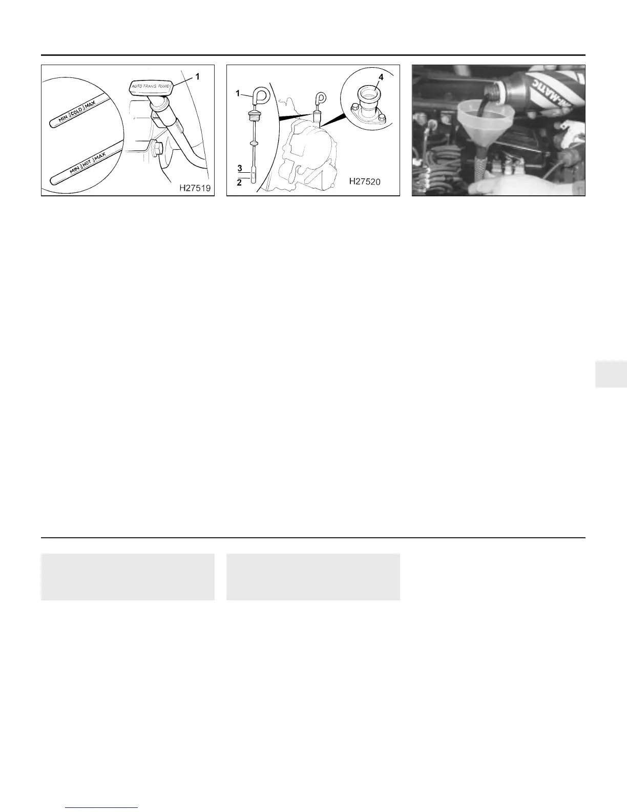
6 Pull the dipstick out again, and note the
fluid level. The level should be between the
“MIN” and “MAX” marks, on the side of the
dipstick marked “HOT” (see illustration). If
the level is on the “MIN” mark, stop the
engine, and add the specified automatic
transmission fluid through the dipstick tube,
using a clean funnel if necessary. It is
important not to introduce dirt into the
transmission when topping-up.
7 Add the fluid a little at a time, and keep
checking the level as previously described
until it is correct. The difference between the
“MIN” and “MAX” marks on the dipstick is
approximately 0.3 litre.
V6 engine models
8 Park the vehicle on level ground, apply the
handbrake, and start the engine. While the
engine is idling, depress the brake pedal and
move the selector lever to the “P” (PARK)
position.
9 Switch off the engine and wait one minute.
10 Remove the dipstick from its tube which
is located at the rear left-hand side of the
engine. The dipstick is mounted low down, on
top of the transmission casing and access is
not very good (see illustration). Note the
condition and colour of the fluid on the
dipstick.
11 Wipe the fluid from the dipstick with a
clean rag, and re-insert it into the filler tube
until the cap seats.
12 Pull the dipstick out again, and note the
fluid level. The level should be within the
shaded sector on the blade. If the level is
below or very near to the bottom of the
shaded sector, add the specified automatic
transmission fluid through the dipstick tube,
using a clean funnel (see illustration). It is
important not to introduce dirt into the
transmission when topping-up.
13 Add the fluid a little at a time, and keep
checking the level as previously described
until it is correct. The difference between the
upper and lower part of the shaded sector is
approximately 0.9 litre.
All models
14 The need for regular topping-up of the
transmission fluid indicates a leak, which
should be found and rectified without delay.
15 The condition of the fluid should also be
checked along with the level. If the fluid at the
end of the dipstick is black or a dark reddish-
brown colour, or if it has a burned smell, the
fluid should be changed. If you are in doubt
about the condition of the fluid, purchase
some new fluid, and compare the two for
colour and smell.
Every 24 000 miles 1•23
31.12 Add the specified automatic
transmission fluid through the dipstick
tube, using a clean funnel
31.10 Automatic transmission fluid level
dipstick (1), Lower (2) and upper (3) shaded
sector and dipstick tube (4)
31.6 Automatic transmission fluid level
dipstick (1) and level markings on
4-cylinder engine models
1
1380 Rover 800 Series Remake
Every 24 000 miles or 2 years, whichever occurs first
32 Timing belt condition and
tension check
4
1 The manufacturers have increased the
service interval for checking the timing belt
condition and tension on certain engines, due
to the introduction of automatic tensioners
and improvements in timing belt construction
and manufacture. However, the conse-
quences of timing belt failure can be very
expensive in terms of possible engine damage
and it is still worthwhile to check the belt at
the shorter intervals given in this schedule.
The procedures vary considerably according
to engine type and model year, and reference
should be made to the appropriate Part of
Chapter 2 for full information.
33 Positive Crankcase
Ventilation (PCV) system
check
1
1 The function of the crankcase ventilation
system is to reduce the emission of unburned
hydrocarbons from the crankcase, and to
minimise the formation of oil sludge. By
ensuring that a depression is created in the
crankcase under most operating conditions,
particularly at idle, and by positively inducing
fresh air into the system, the oil vapours and
“blow-by” gases collected in the crankcase
are drawn from the crankcase, through the air
cleaner or oil separator, into the inlet tract, to
be burned by the engine during normal
combustion.
2 On four cylinder engines, the main
components of the system are an oil
separator, diverter valve and associated
hoses. Checking of the system consists of a
simple visual check of the component hoses
and their connections.
3 On V6 engines the crankcase ventilation
system main components are a PCV valve,
located in the breathing chamber of the front
camshaft cover, and the hoses that connect
to the internal channels in the inlet manifold.
As with 4-cylinder engines, checking is limited
to merely a visual hose condition check.
Accurate checking of the PCV valve should be
entrusted to a dealer.
4 Check that all components of the system
are securely fastened, correctly routed (with
no kinks or sharp bends to restrict flow) and in
sound condition; renew any worn or damaged
components.
 Loading...