3 Disable the ignition system by
disconnecting the LT wiring connectors from
the ignition coil. Refer to Chapter 5 for further
information.
4 Fit a compression tester to the No 1
cylinder spark plug hole - the type of tester
which screws into the plug thread is to be
preferred.
5 Arrange for an assistant to hold the
accelerator pedal fully depressed to the floor
while at the same time cranking the engine
over several times on the starter motor.
Observe the compression gauge reading. The
compression will build up fairly quickly in a
healthy engine. Low compression on the first
stroke, followed by gradually increasing
pressure on successive strokes indicates
worn piston rings. A low compression on the
first stroke which does not rise on successive
strokes, indicates leaking valves or a blown
head gasket (a cracked cylinder head could
also be the cause). Deposits on the underside
of the valve heads can also cause low
compression. Record the highest gauge
reading obtained, then repeat the procedure
for the remaining cylinders.
6 Due to the variety of testers available, and
the fluctuation in starter motor speed when
cranking the engine, different readings are
often obtained when carrying out the
compression test. However, the most
important factor is that the compression
pressures are uniform in all cylinders, and that
is what this test is mainly concerned with.
7 Add some engine oil (about three squirts
from a plunger type oil can) to each cylinder
through the spark plug holes and repeat the
test.
8 If the compression increases after the oil is
added it is indicative that the piston rings are
definitely worn. If the compression does not
increase significantly, the leakage is occurring
at the valves or the head gasket. Leakage
past the valves may be caused by burned
valve seats and/or faces or warped, cracked
or bent valves.
9 If two adjacent cylinders have equally low
compressions, it is most likely that the head
gasket has blown between them. The
appearance of coolant in the combustion
chambers or crankcase would verify this
condition.
10 If one cylinder is about 20 percent lower
than the other, and the engine has a rough
idle, a worn lobe on the camshaft could be the
cause.
11 On completion of the checks, refit the
spark plugs and reconnect the LT wiring at
the ignition coil.
4 Camshaft covers -
removal and refitting
1
“M” series engines
Removal
1 Detach the breather hose from the rear of
the inlet camshaft cover.
2 On cars with multi-point fuel injection,
release the plastic covers then undo the two
bolts securing the plenum chamber support
brackets to the plenum chamber.
3 Undo the two bolts and lift off the spark
plug cover from the centre of the cylinder
head. Note that the spark plug HT lead
grommet engages with the end of the cover,
and on certain models, an accelerator cable
support bracket is also retained by the right-
hand cover bolt.
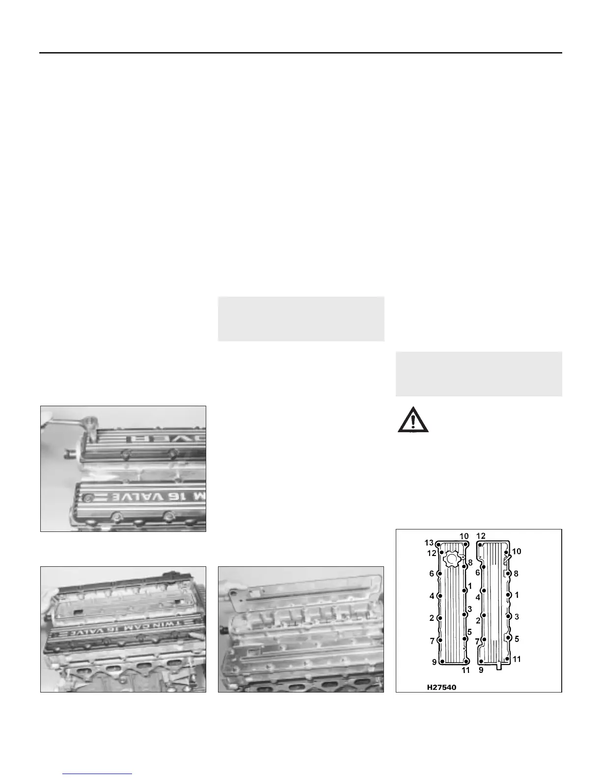
4 Undo the ten bolts securing each camshaft
cover to its respective camshaft housing, and
lift off the two covers (see illustrations).
5 Withdraw the baffle plates, taking care not
to damage the sealing edges on both sides of
the plates (see illustration).
Refitting
6 Refitting is a reversal of removal. Renew the
baffle plates if their sealing edges are
damaged. Tighten the bolts to the specified
torque.
“T” series engines
Removal
7 Detach the breather hoses from the side
and rear of the inlet camshaft cover.
8 Undo the two bolts securing the plenum
chamber support brackets to the plenum
chamber.
9 Undo the four screws and lift off the spark
plug cover between the two camshaft covers.
10 Working from the centre outwards
slacken then remove the ten bolts (inlet
camshaft cover), or 12 bolts (exhaust
camshaft cover) and lift off the two covers.
11 Withdraw the baffle plates, taking care not
to damage the sealing edges on both sides of
the plates.
Refitting
12 Refitting is a reversal of removal. Renew
the baffle plates if their sealing edges are
damaged. Tighten the cover bolts to the
specified torque in the sequence shown (see
illustration).
5 Inlet manifold -
removal and refitting
1
Warning: Petrol is extremely
flammable, so take extra
precautions when disconnecting
any part of the fuel system.
Don’t smoke, or allow naked flames or
bare light bulbs in or near the work area.
Don’t work in a garage where a natural
gas appliance (such as a clothes dryer or
water heater) is installed. If you spill petrol
on your skin, rinse it off immediately. Have
a fire extinguisher rated for petrol fires
handy, and know how to use it.
2A•4 4-cylinder engine – in-car engine repair procedures
4.12 Camshaft cover tightening sequence
for “T” series engines
4.5 Remove the baffle plates over the
camshafts
4.4b . . . and remove the covers
4.4a Undo the camshaft cover retaining
bolts . . .
1380 Rover 800 Series Remake
 Loading...