Single-point fuel injection
engines
Removal
1 Disconnect the battery negative (earth) lead
(refer to Chapter 5, Section 1).
2 Refer to Chapter 4A, and remove the air
cleaner air box.
3 Relieve the fuel system pressure as
described in Chapter 4A, Section 5.
4 Release the hose clips and disconnect the
two fuel hoses from the fuel pipes (see
illustration).
5 Refer to Chapter 4A, Section 12, and
remove the throttle body.
6 Refer to Chapter 1 and drain the cooling
system.
7 Undo the brake servo banjo hose union at
the manifold, and recover the two copper
washers (see illustration).
8 Slacken the hose clip and disconnect the
coolant hose from the right-hand end of the
manifold (see illustration).
9 Disconnect the vacuum hoses from the left-
hand end of the manifold, after noting their
respective positions for reassembly.
10 Slacken the hose clip and disconnect the
remaining coolant hose from the manifold.
11 Undo the bolt securing the manifold to the
support bracket under the coolant hose
outlet.
12 Undo the bolt securing the upper end of
the stay bar to the manifold.
13 Apply the handbrake, jack up the front of
the car and support it on axle stands.
14 Undo the manifold stay bar lower
retaining bolt and remove the stay (see
illustration).
15 Release the clip and disconnect the
breather hose from the oil separator (see
illustration).
16 Disconnect the breather hose from the
lower end of the oil separator at the cylinder
block, and at the sump outlet.
17 Disconnect the lead at the oil pressure
switch and disconnect the pressure
transducer lead at the wiring connector.
18 Unscrew the pipe union nut at the oil
pressure switch adaptor.
19 Unscrew the bolt securing the oil pressure
switch adaptor and oil separator to the
cylinder block and remove the adaptor and oil
separator.
20 Disconnect the wiring plug at the knock
sensor on the cylinder block, and the two
leads at the manifold heater temperature
sensor under the manifold (see illustration).
Move the wiring harness clear of the manifold.
21 Slacken the nine nuts and bolts securing
the manifold to the cylinder head.
22 Remove all the bolts followed by the two
nuts, then withdraw the manifold off the studs
and remove it from the engine. Recover the
manifold gasket.
23 Clean the manifold and cylinder head
mating faces, and obtain a new gasket if the
sealing lips of the original are damaged.
Refitting
24 Refitting is a reversal of removal; tighten
the manifold nuts and bolts in the sequence
shown, to the specified torque (see
illustration).
Multi-point fuel injection
engines
Removal
25 Remove the fuel injectors and fuel rail as
described in Section 12 of either Chapter 4B,
for “M” series, or Chapter 4C for “T” series.
26 Release the clip and disconnect the
breather hose from the oil separator.
27 Disconnect the breather hose from the
lower end of the oil separator and the sump
outlet.
28 Disconnect the wires at the oil pressure
switch, oil pressure transducer and knock
sensor.
4-cylinder engine – in-car engine repair procedures 2A•5
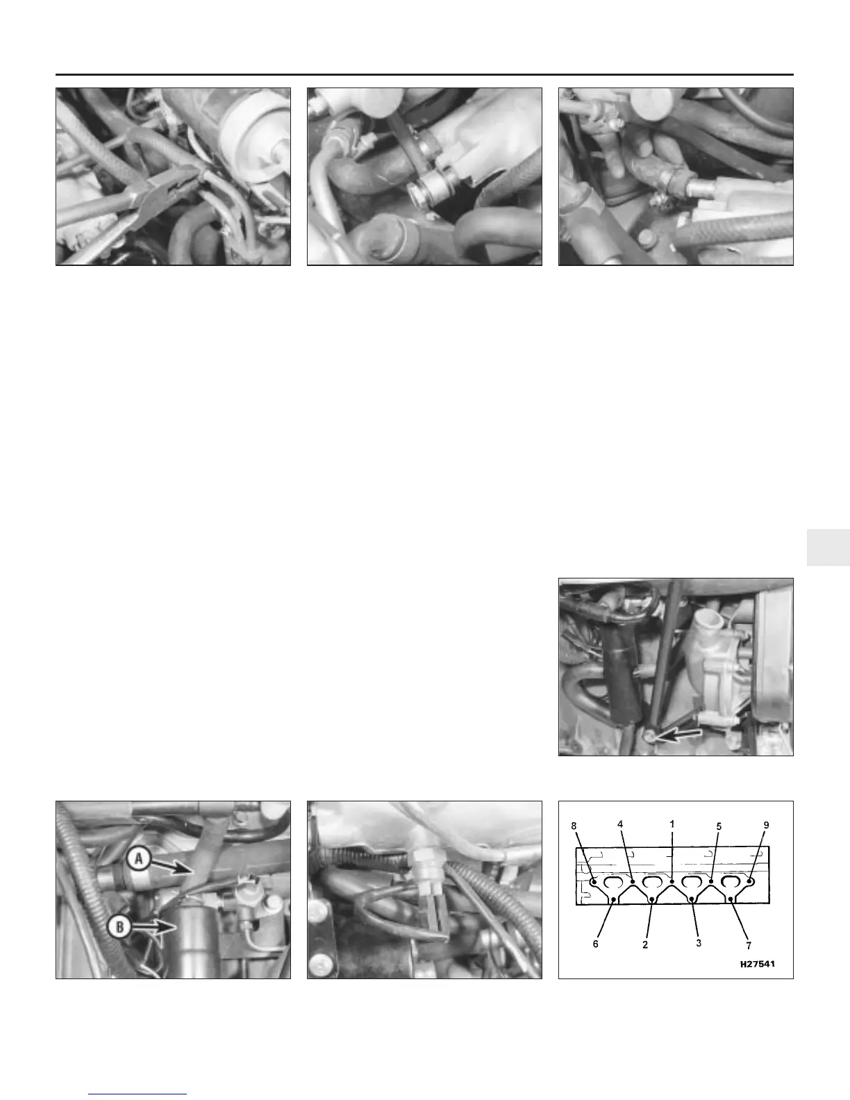
5.8 Disconnect the coolant hose from the
right-hand end of the manifold
5.7 Undo the brake servo banjo hose
union at the manifold
5.4 Release the hose clips and disconnect
the two hoses from the fuel pipes
5.24 Inlet manifold nut and bolt tightening
sequence
5.14 Undo the manifold stay bar lower
retaining bolt (arrowed)
5.20 Disconnect the leads at the manifold
heater temperature sensor
5.15 Disconnect the breather hose (A)
from the oil separator (B)
2A
1380 Rover 800 Series Remake
 Loading...