Early “M” series engines
Removal
1 Disconnect the battery negative (earth) lead
(refer to Chapter 5, Section 1).
2 Slacken the right-hand front wheel nuts,
jack up the front of the car and support it on
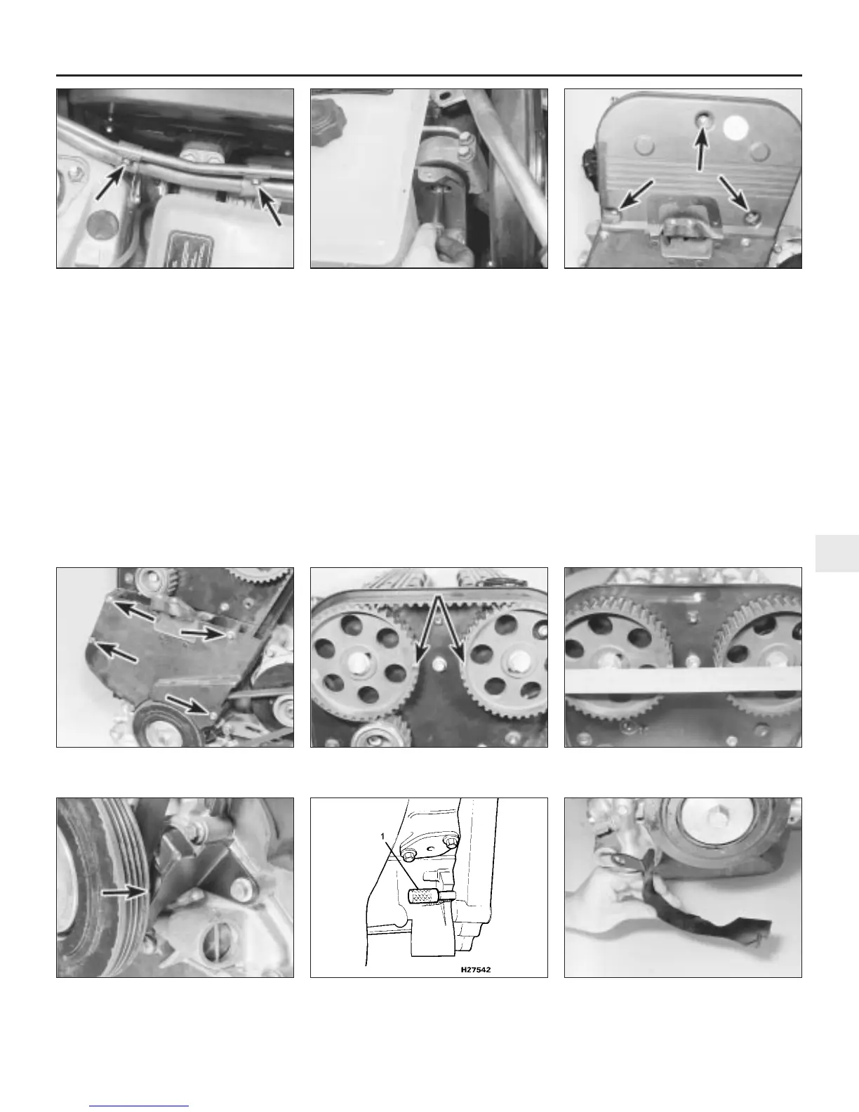
axle stands. Remove the roadwheel.
3 Undo the three bolts and remove the
access panel under the wheelarch.
4 Refer to Chapter 1 and remove the auxiliary
drivebelt.
5 Position a jack and interposed block of
wood under the sump, and just take the
weight of the engine.
6 Undo the bolts securing the power steering
pipe support brackets, and move the pipes
slightly to gain access to the right-hand
engine mounting (see illustration).
7 Undo the engine mounting through-bolt,
and recover the special nut. Note that the
forked end of the nut plate locates over a stud
on the body bracket (see illustration).
8 Undo the two bolts securing the engine
mounting to its mounting bracket, and remove
the mounting.
9 Raise the engine slightly, then undo the
three bolts and lift off the timing belt upper
cover (see illustration).
10 Undo the four bolts and remove the timing
belt lower cover (see illustration).
11 Using a socket or spanner on the
crankshaft pulley, turn the crankshaft in an
anti-clockwise direction until the timing
notches on the camshaft sprockets are facing
each other and aligned horizontally (see
illustrations). The notch on the crankshaft
pulley should also be aligned with the edge of
the metal bracket which forms the timing belt
bottom cover (see illustration). In this
position, the crankshaft is at 90º BTDC, with
No 1 piston on its compression stroke.
12 If required, the crankshaft can be locked in
this position, by inserting a dowel rod or drill
through the hole in the transmission adaptor
plate, near to the lower edge of the cylinder
block on the front-facing side of the engine (see
illustration). The dowel or drill will then engage
with a corresponding hole in the flywheel.
13 Undo the three bolts and remove the
timing belt bottom cover (see illustration).
4-cylinder engine – in-car engine repair procedures 2A•7
7.9 Timing belt upper cover retaining bolts
(arrowed)
7.7 Undo the engine right-hand mounting
through-bolt
7.6 Undo the bolts securing the power
steering pipe support brackets (arrowed)
7.13 Removing the timing belt bottom
cover
7.12 Lock the crankshaft by inserting a
dowel rod or drill (1) through the hole in
the transmission adaptor plate
7.11c Crankshaft pulley timing notch
(arrowed) aligned with timing belt bottom
cover
7.11b . . . then check their horizontal
alignment with a straight edge
7.11a Turn the crankshaft to align the
sprocket timing marks (arrowed) . . .
7.10 Timing belt lower cover retaining
bolts (arrowed)
2A
1380 Rover 800 Series Remake
 Loading...