Inspection
17 Clean and inspect the various
components removed for signs of excessive
wear.
18 Examine the camshaft bearing journals
and lobes for damage or wear. If evident, a
new camshaft must be fitted or one that has
been renovated by a company specialising in
exchange components.
19 The camshaft bearing bore diameters in
the cylinder head should be measured and
checked against the tolerances specified. A
gauge will be required for this but if not
available, check for excessive movement
between the camshaft journals and the
bearings. Alternatively, the Plastigage
method, described in Part C of this Chapter,
for main and big-end bearing running
clearance checks, can be used. If the
bearings are found to be unacceptably worn,
either a new camshaft or a new cylinder head
is required as the bearings are machined
directly in the head.
20 It is seldom that the hydraulic tappets are
badly worn in the cylinder head bores but
again, if the tappets are scored, or the bores
are found to be worn beyond an acceptable
level, either the tappet(s) or the complete
cylinder head must be renewed.
21 If the contact surface of the cam lobes
show signs of depression or grooving, note
that they cannot be renovated by grinding as
the hardened surface will be removed and the
overall length of the tappet(s) will be reduced.
The self-adjustment point of the tappet will be
exceeded as a result, so that the valve
adjustment will be affected and they will then
be noisy in operation. Therefore, renewal
of the camshaft is the only remedy in this
case.
Refitting
22 Remove all traces of sealant from the
camshaft housing retaining bolt holes in the
cylinder head, using an M8 x 1.25 mm tap.
Alternatively, use one of the old bolts with two
file grooves cut into its threads. Also ensure
that there is no oil remaining at the bottom of
the bolt holes.
23 Thoroughly lubricate the tappet bores in
the cylinder head, and refit the tappets in their
original positions.
24 Lubricate the camshaft journals and
lobes, then place the camshafts in position.
Temporarily place the sprockets over the
ends of the camshafts, and position the
camshafts in the cylinder head so that the
sprocket timing marks are horizontal and
towards each other.
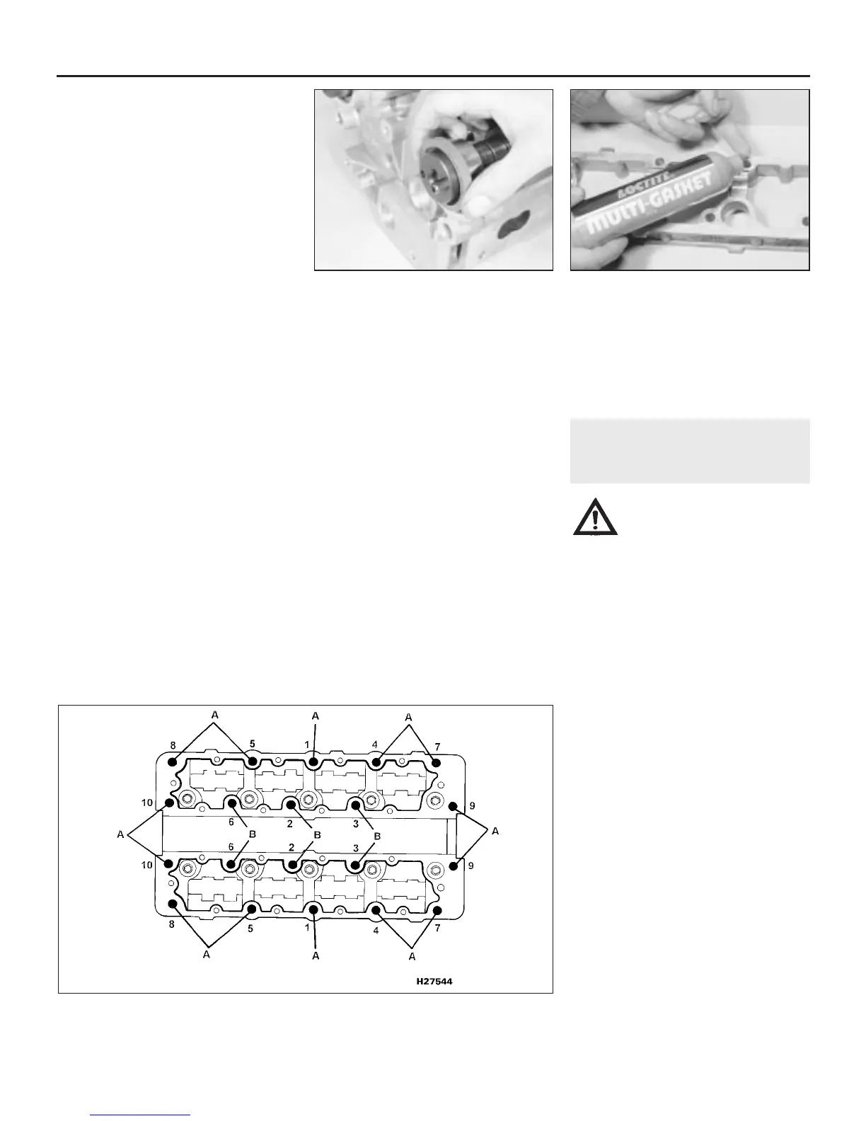
25 Lubricate the sealing lips of the new oil
seals, carefully ease them over the camshaft
journals, and position them against the
shoulder in the cylinder head (see illustration).
26 Apply a thin bead of Loctite sealant 574 to
the camshaft housing-to-cylinder head mating
face, then place both housings in position on
the cylinder head (see illustration).
27 Fit new housing retaining bolts (3 plain
bolts and 7 patch bolts for each housing) and
tighten them in the order shown (see
illustration). Note the locations of the two
types of bolt.
28 The remainder of refitting is a reversal of
removal. When the engine is finally started, be
prepared for a considerable rattle from the
tappets until they completely fill with oil. This
may take a few minutes, and will be more
pronounced if any of the tappets have been
renewed.
12 Cylinder head -
removal and refitting
4
Warning: Petrol is extremely
flammable, so take extra
precautions when disconnecting
any part of the fuel system.
Don’t smoke, or allow naked flames or
bare light bulbs in or near the work area.
Don’t work in a garage where a natural
gas appliance (such as a clothes dryer or
water heater) is installed. If you spill petrol
on your skin, rinse it off immediately. Have
a fire extinguisher rated for petrol fires
handy, and know how to use it.
Single-point fuel injection
engines
Removal
1 Drain the cooling system as described in
Chapter 1.
2 Remove the air cleaner, air box and intake
trunking as described in Chapter 4A.
3 Remove the timing belt as described in
Section 7 or 8, according to engine type.
4 Remove the camshaft covers as described
in Section 4.
5 Undo the nuts and separate the exhaust
front pipe from the manifold flange. Recover
the gasket.
6 Slacken the clips and disconnect the
radiator top hose, and the expansion tank
hose at the thermostat housing.
7 Disconnect the wiring multiplug at the
coolant temperature sensor.
8 Undo the brake servo vacuum hose banjo
union bolt on the right-hand side of the inlet
manifold, and recover the two copper
washers.
9 Slacken the clip and disconnect the heater
hose at the inlet manifold, behind the brake
servo vacuum hose.
2A•12 4-cylinder engine – in-car engine repair procedures
11.26 Apply sealant to the camshaft
housing mating face
11.25 Fitting the camshaft oil seals
1380 Rover 800 Series Remake
11.27 Camshaft housing retaining bolt identification and tightening sequence
A Patch bolt locations B Plain bolt locations
 Loading...