10 Undo the bolt securing the stay bar to the
inlet manifold, below the heater hose.
11 Slacken the clips and disconnect the
heater bypass hose at the thermostat
housing.
12 Slacken the clip and disconnect the
heater hose at the other end of the bypass
pipe.
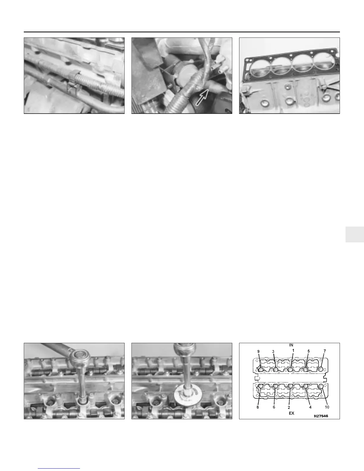
13 Undo the bolts securing the bypass pipe
to the exhaust manifold, cylinder head and
main coolant pipe, release the clips securing
the wiring harness, and remove the bypass
pipe from the engine (see illustration).
14 Slacken the clip and disconnect the
coolant hose at the left-hand end of the inlet
manifold.
15 Disconnect the vacuum hoses from the
inlet manifold, adjacent to the coolant hose.
Mark the location of each hose as it is
disconnected.
16 Undo the bolt securing the support
bracket to the inlet manifold, below the
vacuum hoses.
17 At the rear of the engine below the inlet
manifold, release the wire clip and detach the
breather hose from the top of the oil
separator. Also detach the hose from the
crankcase ventilation system diverter valve
(see illustration).
18 Disconnect the two wires to the inlet
manifold heater temperature sensor, on the
underside of the manifold, and the single lead
to the manifold heater at the wiring connector.
19 Slacken the accelerator cable locknuts,
and unscrew the lower locknut off the outer
cable end. Open the throttle at the throttle
cam, slip the cable end out of the cam slot,
and remove the cable from the support
bracket. Release the cable from the camshaft
cover support bracket, and place it clear of
the engine.
20 On automatic transmission models,
disconnect the kickdown cable, using the
same procedure as for the accelerator cable.
21 Disconnect the wiring multiplugs at the
idle speed stepper motor, the fuel injector,
and the throttle potentiometer. Move the
wiring harness clear of the cylinder head.
22 Place absorbent rags around the fuel filter
outlet union banjo bolt on the left-hand side of
the filter, then slowly unscrew the bolt to
release the fuel system pressure. Remove the
bolt and recover the two copper washers after
the pressure has been released. Tape over the
filter orifice and banjo union to prevent fuel
loss and dirt ingress.
23 Disconnect the fuel return hose at the
pipe below the fuel filter.
24 Remove the dipstick from the dipstick
tube.
25 On cars fitted with a rear-mounted power
steering pump, extract the circlip from the end
of the power steering pump drivebelt tension
adjuster bolt. Slide the adjuster rearwards,
and undo all the accessible bolts securing the
adjuster bracket to the cylinder head. Now
move the adjuster the other way, and undo
the remaining bolts, then remove the adjuster
assembly complete.
26 Progressively slacken all the cylinder head
retaining bolts, in the reverse sequence to that
shown (see illustration 12.32c). Remove the
bolts when all have been slackened.
27 With the help of an assistant, lift the
cylinder head, complete with manifolds, off
the engine. If the head is stuck, it can be
carefully levered up using a large screwdriver
between the cylinder block and the protruding
cylinder head flanges. Do not insert the
screwdriver under the head-to-block mating
face. Place the head on blocks on the bench
to protect the valves.
28 Remove the cylinder head gasket from the
block.
29 Prior to refitting, ensure that the cylinder
block and head mating faces are thoroughly
clean and dry, with all traces of old gasket
removed. Clean the threads of the retaining
bolts, and remove any oil, water and thread
sealer from the bolt holes.
Refitting
30 Locate a new gasket over the dowels on
the cylinder block (see illustration).
31 Check that the crankshaft is still
positioned at the 90º BTDC position, and that
the timing marks on the camshaft sprockets
are aligned.
32 Lower the cylinder head assembly onto
the gasket, and refit the retaining bolts.
Working in the sequence shown, tighten the
retaining bolts in stages, to the specified
torque and angle settings given in the Specifi-
cations (see illustrations).
33 The remainder of refitting is a reversal of
4-cylinder engine – in-car engine repair procedures 2A•13
12.30 Locate a new cylinder head gasket
over the dowels
12.17 Detach the hose from the diverter
valve (arrowed)
12.13 Release the wiring harness clips
from the bypass pipe
12.32b . . . then angle-tighten the bolts to
the specified angular setting
12.32a Tighten the cylinder head bolts to
the specified torque . . .
2A
1380 Rover 800 Series Remake
12.32c Cylinder head bolt tightening
sequence
 Loading...