removal but refer to the relevant Sections
and Chapters for adjustment details as
necessary.
Multi-point fuel injection
engines
Removal
34 Carry out the operations described in
Paragraphs 1 to 8.
35 On turbocharged engines remove the
exhaust manifold as described in the relevant
part of Chapter 4.
36 Slacken the clip and disconnect the
heater hose at the other end of the bypass
pipe.
37 Undo the bolts securing the bypass pipe
to the exhaust manifold, cylinder head and
main coolant pipe, and remove the bypass
pipe.
38 Slacken the clips and disconnect the two
coolant hoses from the underside of the
throttle housing.
39 At the rear of the engine, disconnect the
wiring multiplugs and leads at the crankshaft
sensor, knock sensor, oil pressure switch and
oil pressure transducer.
40 Disconnect the main engine wiring loom
multiplug(s) on the right-hand side valance as
necessary, to enable part of the loom to be
removed with the cylinder head.
41 Check that all the wiring likely to impede
removal of the cylinder head and its ancillaries
has been disconnected, and the harness
moved clear. It may be necessary to
disconnect additional wiring, depending on
options or additional equipment fitted.
42 Disconnect the breather hoses from the
oil separator.
43 Open the throttle fully by hand, and slip
the accelerator inner cable end out of the slot
on the throttle lever.
44 Slacken the outer cable locknuts, and
unscrew the outer locknut, nearest to the
cable end, fully. Remove the washer and
rubber bush, then withdraw the cable from the
support bracket.
45 On automatic transmission models,
disconnect the kickdown cable, using the
same procedure as for the accelerator cable.
46 Place absorbent rags around the fuel filter
outlet union banjo bolt on the left-hand side of
the filter, then slowly unscrew the bleed screw
in the centre of the bolt to release the fuel
system pressure. Tighten the bleed screw
when the pressure has been released. Undo
the outlet union banjo bolt, and recover the
two copper washers. Tape over the filter
orifice, and banjo union to prevent fuel loss
and dirt entry.
47 Unscrew the union nut and disconnect the
fuel return hose at the fuel pressure regulator,
on the left-hand side of the inlet manifold.
48 Remove the dipstick from the dipstick
tube.
49 On cars fitted with a rear-mounted power
steering pump, extract the circlip from the end
of the power steering pump drivebelt tension
adjuster bolt. Slide the adjuster rearwards,
and undo all the accessible bolts securing the
adjuster bracket to the cylinder head. Now
move the adjuster the other way, and undo
the remaining bolts, then remove the adjuster
assembly complete.
50 Progressively slacken all the cylinder head
retaining bolts, in the reverse sequence to that
shown (see illustration 12.32c). Remove the
bolts when all have been slackened.
51 With the help of an assistant, lift the
cylinder head, complete with manifolds, off
the engine. If the head is stuck, it can be
carefully levered up using a large screwdriver
between the cylinder block and the protruding
cylinder head flanges. Do not insert the
screwdriver under the head-to-block mating
face. Place the head on blocks on the bench
to protect the valves.
52 Remove the cylinder head gasket from the
block.
53 Prior to refitting, ensure that the cylinder
block and head mating faces are thoroughly
clean and dry, with all traces of old gasket
removed. Clean the threads of the retaining
bolts, and remove any oil, water and thread
sealer from the bolt holes.
Refitting
54 Locate a new gasket over the dowels on
the cylinder block.
55 Check that the crankshaft is still
positioned at the 90º BTDC position, and that
the timing marks on the camshaft sprockets
are aligned.
56 Lower the cylinder head assembly onto
the gasket, and refit the retaining bolts.
Working in the sequence shown, tighten the
retaining bolts in stages, to the specified
torque and angle settings given in the Specifi-
cations (see illustration 12.32c).
57 The remainder of refitting is a reversal of
removal but refer to the relevant Sections
and Chapters for adjustment details as
necessary.
13 Sump -
removal and refitting
1
Removal
1 Disconnect the battery negative (earth) lead
(refer to Chapter 5, Section 1).
2 Apply the handbrake, jack up the front of
the car and support it on axle stands.
3 Drain the engine oil as described in Chapter
1.
4 Remove the exhaust front section with
reference to the appropriate Part of Chap-
ter 4.
5 Undo the bolts securing the longitudinal
support member to the underbody
beneath the engine, and remove the
member.
6 Disconnect the crankcase breather
hose from the pipe stub on the side of the
sump.
7 Where applicable, release the turbocharger
oil return hose from the sump.
8 Slacken, then remove, the sump retaining
bolts, noting that the corner bolt on the drain
plug side at the flywheel end is longer than the
rest, and has a flat washer and elongated
washer in addition to the normal spring
washer (see illustration).
9 Withdraw the sump from the crankcase,
tapping it from side to side with a hide or
plastic mallet if it is stuck. Recover the sump
gasket.
10 If the oil pick-up tube and strainer are to
be removed, undo the two bolts securing the
tube flange to the crankcase, and the single
bolt securing the support bracket to the main
bearing cap (see illustration).
11 Slide the support bracket from under the
crankcase breather oil return pipe, and
remove the pick-up pipe and tube from the
crankcase. Recover the O-ring from the pick-
up pipe flange.
12 Clean the sump thoroughly, and remove
all traces of old gasket and sealant from the
mating faces of the sump and crankcase.
13 If removed, clean the pick-up pipe, and
the filter gauze in the strainer.
Refitting
14 Place a new O-ring seal on the pick-up
pipe flange, fit the pipe and strainer assembly,
and secure with the retaining bolts,
2A•14 4-cylinder engine – in-car engine repair procedures
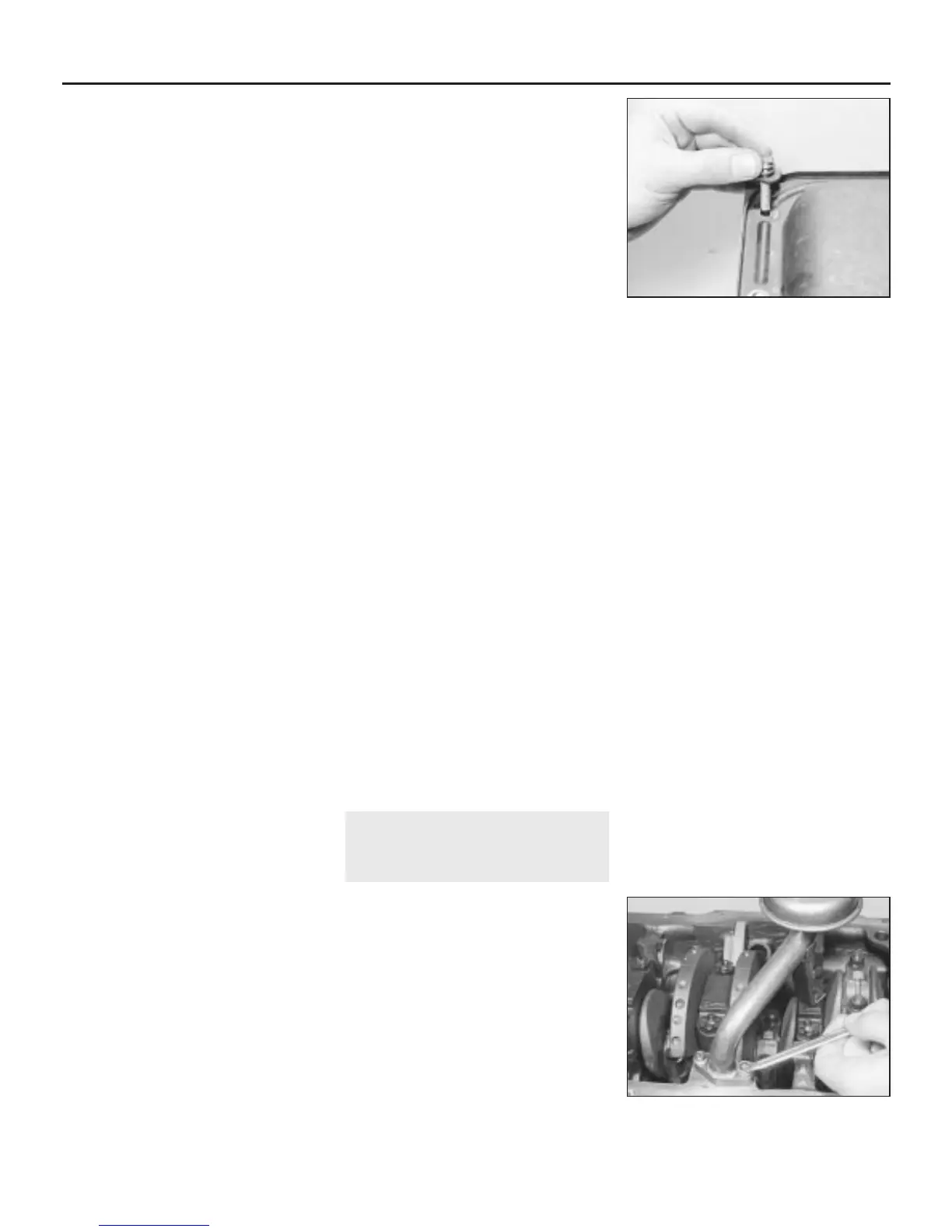
13.8 Sump special retaining bolt
location
1380 Rover 800 Series Remake
13.10 Undo the two pick-up pipe-to-
crankcase bolts
 Loading...