the old ring then splitting it with a chisel. The
new ring must then be heated so that it
expands slightly, and allowed to cool when in
position on the flywheel. As it cools, it
contracts to a smaller diameter than the
flywheel so as to provide a tight interference
fit. The temperatures involved in this operation
are critical to avoid damaging the ring gear,
and the work should be carried out by a Rover
dealer or motor engineering works.
5 The clutch friction surface on the flywheel
should be checked for grooving or cracks, the
latter being caused by overheating. If these
conditions are evident, renewal of the flywheel
is necessary.
6 On manual and automatic transmission
models, check the condition of the reluctor
ring teeth. If any are bent, broken. or in any
way damaged, renew the ring, which is bolted
to the flywheel or driveplate.
Refitting
7 Refitting is a reversal of removal. Tighten
the new bolts to the specified torque,
then bend over the tabs of a new locking
plate.
18 Engine/transmission
mountings -
inspection and renewal
1
Inspection
1 The engine/transmission mountings seldom
require attention, but broken or deteriorated
mountings should be renewed immediately, or
the added strain placed on the driveline
components may cause damage or wear (see
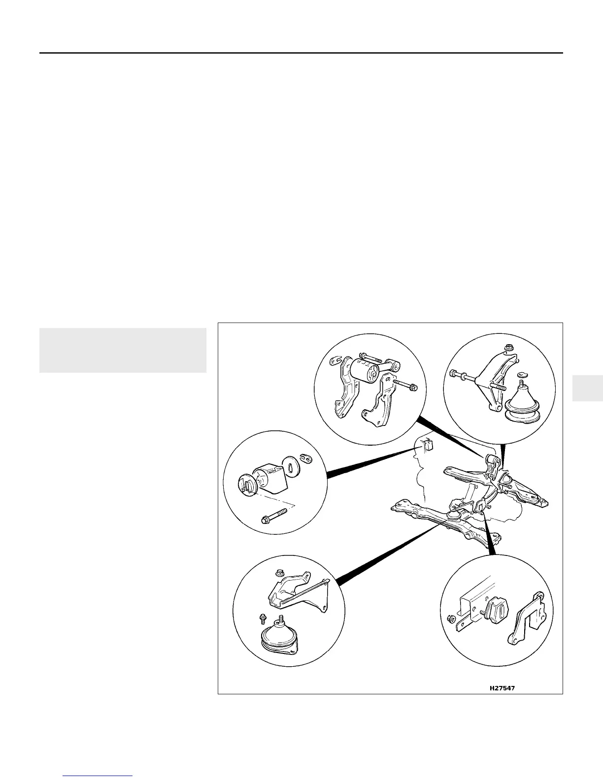
illustration).
2 During the check, the engine/transmission
unit must be raised slightly, to remove its
weight from the mountings.
3 Raise the front of the vehicle, and support it
securely on axle stands. Position a jack under
the sump, with a large block of wood between
the jack head and the sump, then carefully
raise the engine/transmission just enough to
take the weight off the mountings.
4 Check the mountings to see if the rubber is
cracked, hardened or separated from the
metal components. Sometimes the rubber will
split right down the centre.
5 Check for relative movement between each
mounting’s brackets and the engine/
transmission or body (use a large screwdriver
or lever to attempt to move the mountings). If
movement is noted, lower the engine and
check-tighten the mounting fasteners.
Renewal
Front mounting
6 Remove the battery as described in
Chapter 5, then undo the retaining bolts and
remove the battery tray.
7 Remove the air cleaner assembly as
described in the relevant part of Chapter 4.
8 Undo the nut securing the mounting to the
engine mounting bracket, and the two bolts
securing the mounting to the front chassis
member.
9 Using a jack and interposed block of wood,
raise the engine slightly until the mounting
stud can be withdrawn from the bracket, then
remove the mounting from the car.
10 Renew the mounting if it shows any sign
of damage, contamination or separation of the
rubber-to-metal bond.
11 Refitting is a reversal of removal, but
ensure that the small peg on the mounting top
face engages with the hole in the bracket, and
tighten the bolts and nut to the specified
torque (Chapter 2, Part C).
Rear mounting
12 Remove the air cleaner assembly and air
intake trunking as described in the relevant
part of Chapter 4.
13 Jack up the front of the car and support it
on axle stands.
14 Undo the bolts and remove the
longitudinal support member from beneath
the engine.
15 Support the engine and transmission
assembly on a jack with interposed block of
wood.
16 Undo and remove all the nuts and bolts
securing the mounting to its mounting bracket
and chassis member, and the mounting
bracket to the engine.
17 Withdraw the mounting bracket from
below, followed by the mounting. If there is a
spacer located between the mounting and
mounting bracket, retain this for refitting with
the existing mounting, but discard it if the
mounting is being renewed.
18 Renew the mounting if it shows any sign
of damage, contamination or separation of the
rubber-to-metal bond.
19 Refitting is a reversal of removal, but
ensure that the small peg on the mounting top
face engages with the hole in the bracket, and
tighten the bolts and nut to the specified
torque (Chapter 2, Part C).
Right-hand mounting
20 Position a jack and interposed block of
wood under the sump, and just take the
weight of the engine.
21 Undo the bolts securing the power
steering pipe support brackets, and move the
4-cylinder engine – in-car engine repair procedures 2A•17
18.1 Engine mounting components (manual transmission shown - automatic
transmission similar)
2A
1380 Rover 800 Series Remake
 Loading...