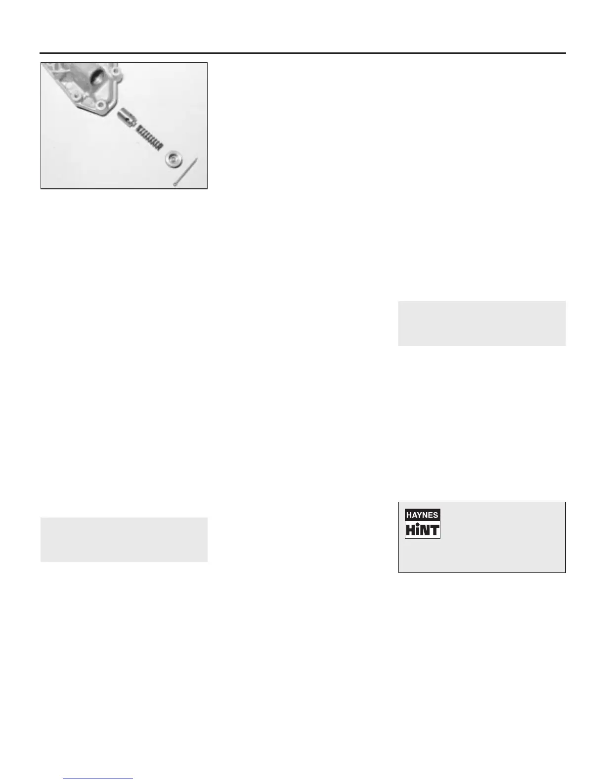
2 To remove the pressure relief valve
components, extract the split pin and
withdraw the plug cap, spring and relief valve
plunger (see illustration).
3 Using a screwdriver, prise out the
crankshaft front oil seal from the oil pump
housing.
Inspection
4 Inspect the condition of the inner and outer
rotors for visual signs of scoring or wear
ridges. Note that the pump internal parts are
not available separately, and if there is any
sign of wear, a complete new oil pump and
housing assembly must be obtained.
5 Check the plunger for scoring or wear
ridges, and renew if necessary. Also renew
the plug cap O-ring if it shows signs of
deterioration.
Reassembly
6 Liberally lubricate the pump rotors to prime
the pump, then refit the pump cover and
secure with the four Torx bolts.
7 Lubricate the relief valve components with
engine oil, then refit the plunger, spring and
plug cap. Secure the cap with a new split pin.
8 Place a new oil seal in position, and
carefully tap it home with the aid of a mallet,
block of wood and the old oil seal.
16 Crankshaft oil seals -
renewal
4
Front oil seal
1 Remove the timing belt as described in
Section 7 or 8, according to engine type.
2 On early “M” series engines, remove the
starter motor as described in Chapter 5. Using
a socket and long handle, slacken the
crankshaft pulley centre retaining bolt. Lock
the flywheel ring gear, through the starter
motor aperture, using a large screwdriver or
similar tool to prevent the crankshaft rotating
as the pulley bolt is undone. Remove the bolt
and withdraw the pulley.
3 On later “M” series engines and all “T”
series engines, withdraw the sprocket from
the crankshaft.
4 Remove the Woodruff key from the slot in
the crankshaft.
5 Punch or drill two small holes opposite
each other in the seal. Screw a self-tapping
screw into each, and pull on the screws with
pliers to extract the seal.
6 Clean the seal housing, and polish off any
burrs or raised edges, which may have
caused the seal to fail in the first place.
7 Lubricate the lips of the new seal with clean
engine oil and carefully locate the seal over
the crankshaft and into the housing.
8 Using a tubular drift which bears on the
hard outer edge of the seal, drive the seal into
the housing until it is flush with the housing
face.
9 Refit the Woodruff key to the crankshaft.
10 On later “M” series engines and all “T”
series engines, refit the sprocket to the
crankshaft.
11 On early “M” series engines, refit the
crankshaft pulley and tighten the retaining bolt
to the specified torque. Prevent the crankshaft
rotating using the same method as used for
removal when tightening the bolt. Refit the
starter motor as described in Chapter 5.
12 Refit the timing belt as described in
Section 7 or 8 as applicable.
Rear oil seal
13 Remove the flywheel/driveplate as
described in Section 17.
“M” series engines
14 Punch or drill two small holes opposite
each other in the seal. Screw a self-tapping
screw into each, and pull on the screws with
pliers to extract the seal.
15 Clean the seal housing, and polish off any
burrs or raised edges, which may have
caused the seal to fail in the first place.
16 Lubricate the lips of the new seal with
clean engine oil and carefully locate the seal
on the end of the crankshaft.
17 Using a tubular drift which bears on the
hard outer edge of the seal, drive the seal into
the housing until it is flush with the housing
face.
18 Clean off any surplus oil then refit the
flywheel/driveplate as described in Sec-
tion 17.
“T” series engines
19 Drain the engine oil as described in
Chapter 1.
20 Slacken all the sump securing bolts in a
progressive sequence, but do not slacken the
three at the timing belt end.
21 Completely remove the two bolts at the
other end, securing the sump to the oil seal
carrier.
22 Undo the five bolts and carefully remove
the oil seal carrier from the cylinder block
dowels and crankshaft. Take great care not to
damage the sump gasket as the carrier is
removed.
23 Note that the oil seal carrier and the oil
seal itself, are supplied as an assembly; the
seal is not available separately.
24 Before refitting, inspect the sump gasket;
if it was damaged in any way during removal it
must be renewed.
25 Clean the end of the crankshaft, and
polish off any burrs or raised edges, which
may have caused the seal to fail in the first
place.
26 Lubricate the lips of the new seal with
clean engine oil and carefully locate the seal
on the end of the crankshaft.
27 Push the oil seal carrier into position over
the locating dowels and refit the retaining
bolts. Progressively tighten the carrier bolts to
the specified torque, starting with the two at
the bottom, then the two in the centre, and
finally the one at the top.
28 Tighten the sump bolts to the specified
torque, in the correct sequence (see Sec-
tion 13).
29 Refit the flywheel/driveplate as described
in Section 17. Refill the engine with oil on
completion of refitting, and check for leaks
around the sump flange when the engine is
run.
17 Flywheel/driveplate -
removal, inspection and
refitting
3
Removal
1 With the engine removed from the car and
separated from the transmission, or with the
transmission removed as described in
Chapter 7, remove the clutch assembly
(manual transmission) as described in Chapter
6.
2 Where fitted, knock back the tabs of the
locking plate, using a screwdriver or small
chisel, and undo the six flywheel/driveplate
retaining bolts. Note that the retaining bolts
are of the encapsulated type, incorporating a
locking compound in their threads, and new
bolts must be obtained for reassembly.
3 Lift off the locking plate, then withdraw the
flywheel/driveplate from the crankshaft. On
automatic transmission models, recover the
spacer from the end of the crankshaft.
Inspection
4 Inspect the starter ring gear on the flywheel
or driveplate for wear or broken teeth. If
evident, the ring gear should be renewed. On
automatic transmission models, the ring gear
is bolted to the driveplate, and renewal is
straightforward. On manual transmission
models however, the ring gear is a shrink fit
on the flywheel, and renewal entails drilling
2A•16 4-cylinder engine – in-car engine repair procedures
15.2 Oil pressure relief valve
components
1380 Rover 800 Series Remake
To prevent the flywheel
turning, lock the ring gear
teeth using a small strip of
angle iron engaged in the
teeth and against the adaptor plate
dowel.
 Loading...