5 Remove the access cover under the right-
hand wheelarch.
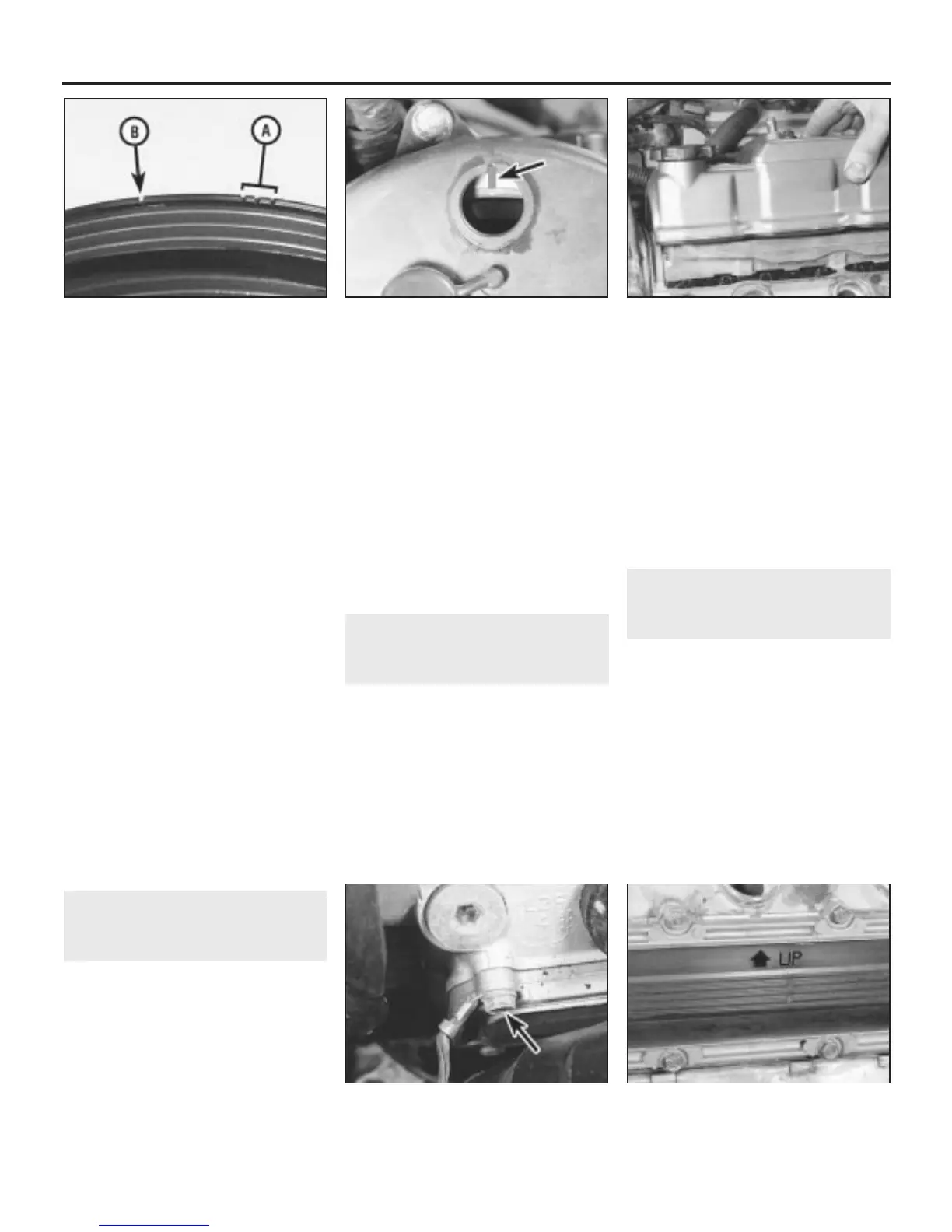
6 Using a socket and bar on the crankshaft
pulley bolt, rotate the crankshaft pulley, in the
normal direction of rotation, until a series of
very small notches on the pulley inner rim
come into view. The first three notches are the
ignition timing marks and can be ignored. The
next notch (usually coloured white) represents
Top Dead Centre (TDC) for No 1 piston on
compression, and this is the one we’re after
(see illustration).
7 Continue turning the crankshaft until the
TDC notch is aligned with the pointer on the
timing belt cover, just above the pulley. It’s
best to look down at this from the engine
compartment to get the angle right.
8 Now look through the viewing hole on the
front timing belt cover. A paint mark on the
camshaft sprocket rim should be aligned with
the notch at the top of the viewing window
(see illustration). If it isn’t, turn the crankshaft
through one complete revolution and realign
the timing marks as before. The mark on the
camshaft sprocket should now be correctly
aligned. The mark on the rear camshaft
sprocket should also be visible through the
other window.
9 When all the marks are aligned, the engine
is at TDC for No 1 cylinder on compression,
and is correctly positioned for any work that
requires the timing belt to be disturbed.
10 Refit the plugs to the viewing windows on
completion.
5 Camshaft covers -
removal and refitting
1
Removal
1 Release the spark plug HT leads from their
clips on the camshaft covers and move the
leads to one side.
2 Release the clips and disconnect the
breather hoses from the camshaft covers.
3 Disconnect the oil temperature switch
wiring multiplug from the rear camshaft cover.
4 Undo the two bolts and detach the pipe
support brackets from the rear cover.
5 Undo the two bolts securing each camshaft
cover to the cylinder head and lift off the
covers (see illustration). Collect the washers
under the bolt heads, and remove the cover
gaskets.
6 Inspect the cover gasket and the seals on
the retaining bolts and renew any that are
damaged.
7 Clean the cover and mating faces carefully
then, if necessary, fit a new gasket to the
cover, ensuring that it locates in the cover
grooves.
Refitting
8 Refitting is a reversal of removal.
6 Cylinder head side covers -
removal and refitting
1
Removal
1 If the rear cover is being removed, jack up
the front of the vehicle and support it on axle
stands. Access to the rear cover is marginally
better from below.
2 Move the adjacent components clear as
much as possible and undo the side cover
retaining bolts. Note the oxygen sensor wiring
support bracket attachments on one of the
lower bolts and the engine earth lead on the
upper front cover bolt (see illustration).
3 Withdraw the side covers from the cylinder
head being prepared for some oil spillage.
4 Inspect the condition of the cover gasket
and renew it if necessary.
5 Clean the cover and mating faces carefully
then, if necessary, fit a new gasket to the
cover, ensuring that it locates in the cover
grooves.
Refitting
6 Refitting is a reversal of removal. Ensure
that the arrow, and the word UP are at the top
when refitting each cover (see illustration).
7 Exhaust valve rocker
clearances - adjustment
3
Note: This is not a routine maintenance
operation and will only be necessary if the
cylinder head, camshafts or any components
of the valve train have been disturbed or
renewed.
1 Remove the camshaft covers and the
cylinder head side covers as described in
Sections 5 and 6 respectively.
2 Set the engine to TDC for No 1 cylinder on
compression, as described in Section 4.
3 Slacken the rocker arm adjusting screw
locknuts for No 1 cylinder exhaust valves on
the rear cylinder head.
4 Tighten the adjusting screw until it just
contacts the valve, then tighten it a further
2B•4 V6 engine - in-car engine repair procedures
6.6 Ensure that the arrow, and the word
UP are at the top when refitting the side
covers
6.2 Engine earth lead (arrowed) on the
upper front side cover bolt
5.5 Lifting off the front camshaft cover4.8 Paint mark on the camshaft sprocket
rim aligned with the notch at on the
viewing window
4.6 Ignition timing notches (A) and TDC
notch (B) on the crankshaft pulley
1380 Rover 800 Series Remake
 Loading...