(b) Prime the tappet oil feeds in the cylinder
head with oil (see illustration).
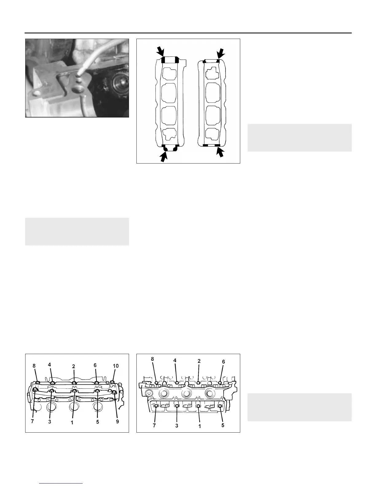
(c) Apply RTV sealant to the ends of the
camshaft carrier before refitting (see
illustration).
(d) Use new gaskets on all joints and tighten
the retaining nuts and bolts to the
specified torque where given. Tighten the
oil gallery bolts in the sequence shown
(see illustration).
(e) Refit all components removed for access
as described in the relevant Sections and
Chapters of this manual.
16 Cylinder head -
removal and refitting
4
Removal
1 Remove the inlet manifold as described in
Section 8.
2 Remove the camshaft and hydraulic
tappets on the side concerned as described in
Section 15.
3 Undo the flange bolts and remove the
exhaust front pipes from the exhaust
manifolds. Recover the flange gaskets.
4 Undo the bolts securing the coolant
connecting pipe. Disconnect the temperature
sensor wiring multiplug, move the wiring
harness aside and remove the connecting
pipe. Recover the sealing O-rings from
the pipe.
5 If removing the front cylinder head,
disconnect the camshaft sensor wiring
multiplug (where fitted).
6 If not already removed, remove the push
rods from their locations and place them in a
marked box to indicate their respective
cylinders.
7 Progressively slacken the cylinder head
retaining bolts a third of a turn at a time, in the
sequence shown until all are slack, then
remove the bolts (see illustration).
8 Lift the cylinder head off the locating
dowels and remove it from the engine. If the
head is stuck, it can be carefully levered up
using a large screwdriver between the
cylinder block and the protruding cylinder
head flanges. Do not insert the screwdriver
under the head-to-block mating face. Place
the head on blocks on the bench to protect
the valves.
9 Remove the cylinder head gasket from the
block.
10 Prior to refitting, ensure that the cylinder
block and head mating faces are thoroughly
clean and dry, with all traces of old gasket
removed. Clean the threads of the retaining
bolts, and remove any oil, water and thread
sealer from the bolt holes.
Refitting
11 Locate a new gasket over the dowels on
the cylinder block.
12 Lower the cylinder head assembly onto the
gasket, and refit the retaining bolts. Working in
the sequence shown, tighten the retaining bolts
to the specified torque (see illustration 16.7).
Note that the cylinder head bolt slackening and
tightening sequence are the same.
13 The remainder of refitting is a reversal of
removal but refer to the relevant Sections and
Chapters of this manual for adjustment
details.
17 Sump -
removal and refitting
1
Removal
1 Disconnect the battery negative (earth) lead
(refer to Chapter 5, Section 1).
2 Apply the handbrake, jack up the front of
the car and support it on axle stands.
3 Drain the engine oil as described in Chapter 1.
4 Remove the exhaust front pipe with
reference to Chapter 4, Part D.
5 Undo the bolts securing the longitudinal
support member to the underbody beneath
the engine, and remove the member.
6 Undo the six nuts and sixteen bolts
securing the sump to the crankcase.
7 Withdraw the sump from the crankcase,
tapping it from side to side with a hide or
plastic mallet if it is stuck. Recover the sump
gasket.
8 If the oil pick-up tube and strainer are to be
removed, undo the two bolts securing the
strainer bracket to the crankcase, and the two
bolts securing the pick-up tube flange to the
oil pump.
9 Remove the pick-up pipe and tube from the
crankcase. Recover the O-ring from the pick-
up pipe flange. Remove the baffle plate from
the cylinder block.
10 Clean the sump, and the mating faces of
both the sump and crankcase thoroughly.
11 If removed, clean the pick-up pipe, and
the filter gauze in the strainer.
Refitting
12 Refitting is a reversal of removal. Use a
new sump gasket and O-ring seal on the pick-
up pipe flange and tighten the sump retaining
nuts and bolts progressively to the specified
torque. Fill the engine with oil as described in
Chapter 1 on completion.
18 Oil cooler and filter head -
removal and refitting
1
Removal
1 Drain the cooling system as described in
Chapter 1.
2B•10 V6 engine - in-car engine repair procedures
16.7 Cylinder head bolt slackening and
tightening sequence
15.31d Oil gallery retaining bolt tightening
sequence
15.31c Apply RTV sealant to the ends of
the camshaft carrier (shown shaded)
before refitting
15.31b Prime the tappet oil feeds in the
cylinder head with oil
1380 Rover 800 Series Remake
H27532
H27533 H27534
 Loading...