31 Undo the three expansion tank retaining
bolts and move the expansion tank to one
side.
32 Jack up the front of the car and support it
on axle stands. Remove the front roadwheels.
33 Undo the bolts and remove the access
panel under the right-hand wheelarch and the
undertray from beneath the wheelarch.
34 Undo the flange bolts and separate the
exhaust front pipes from the manifolds.
Collect the gaskets.
35 Remove the engine oil cooler and filter
head assembly as described in Part B,
Section 18.
36 Undo the retaining bolt and remove the
speedometer transducer assembly from the
rear of the transmission. Move the assembly
clear.
37 Undo and remove the nut from the rear
engine mounting.
38 Undo the nut securing the right-hand
steering knuckle balljoint to the lower
suspension arm, then release the balljoint
from the arm using a universal balljoint
separator tool or two-legged puller.
39 Pull the steering knuckle outwards, then
using a flat bar or large screwdriver, lever
between the driveshaft and intermediate
bearing assembly to release the joint.
40 Move the driveshaft clear, then repeat
these operations on the left-hand driveshaft,
but release it from the differential housing.
41 Attach a hoist using chains attached to
the engine and transmission lifting eyes. Raise
the hoist to just take the weight of the engine.
42 Undo the eight bolts and remove the
longitudinal support member from beneath
the engine.
43 On manual transmission models, undo the
two slave cylinder retaining bolts, collect the
pushrod and move the cylinder aside.
44 On manual transmission models, undo the
bolt in the centre of the transmission steady
rod. Remove the dished washer, slide off the
steady rod and remove the inner flat washer.
Remove the spring clip to expose the
gearchange rod-to-gearchange shaft retaining
roll pin. Using a parallel pin punch, tap out the
roll pin and slide the gearchange rod
rearwards off the shaft.
45 On automatic transmission models, refer
to Chapter 7, Part B and disconnect the
selector cable at the transmission end.
46 Undo the front engine mounting retaining
nut, then undo the three bolts and remove the
mounting bracket from the engine.
47 Undo the right-hand engine mounting
through-bolt, and recover the special nut.
Note that the forked end of the nut plate
locates over a stud on the body bracket.
48 Undo the two bolts securing the right-
hand engine mounting to the engine, and
remove the mounting.
49 Check that all electrical connections
between the engine and the car main wiring
harness have been disconnected and moved
clear. The engine wiring harness stays in situ,
and is removed with the engine assembly.
50 Make a final check that everything
connecting the engine and transmission to the
car has been disconnected and moved well
clear.
51 Support the engine on a jack with
interposed block of wood positioned under
the sump. take the weight of the
engine/transmission on the jack so that the
hoist can be lowered slightly. Reposition the
lifting chains so that the engine will adopt
approximately a 30º angle to the horizontal as
it is lifted out, with the timing belt end
uppermost.
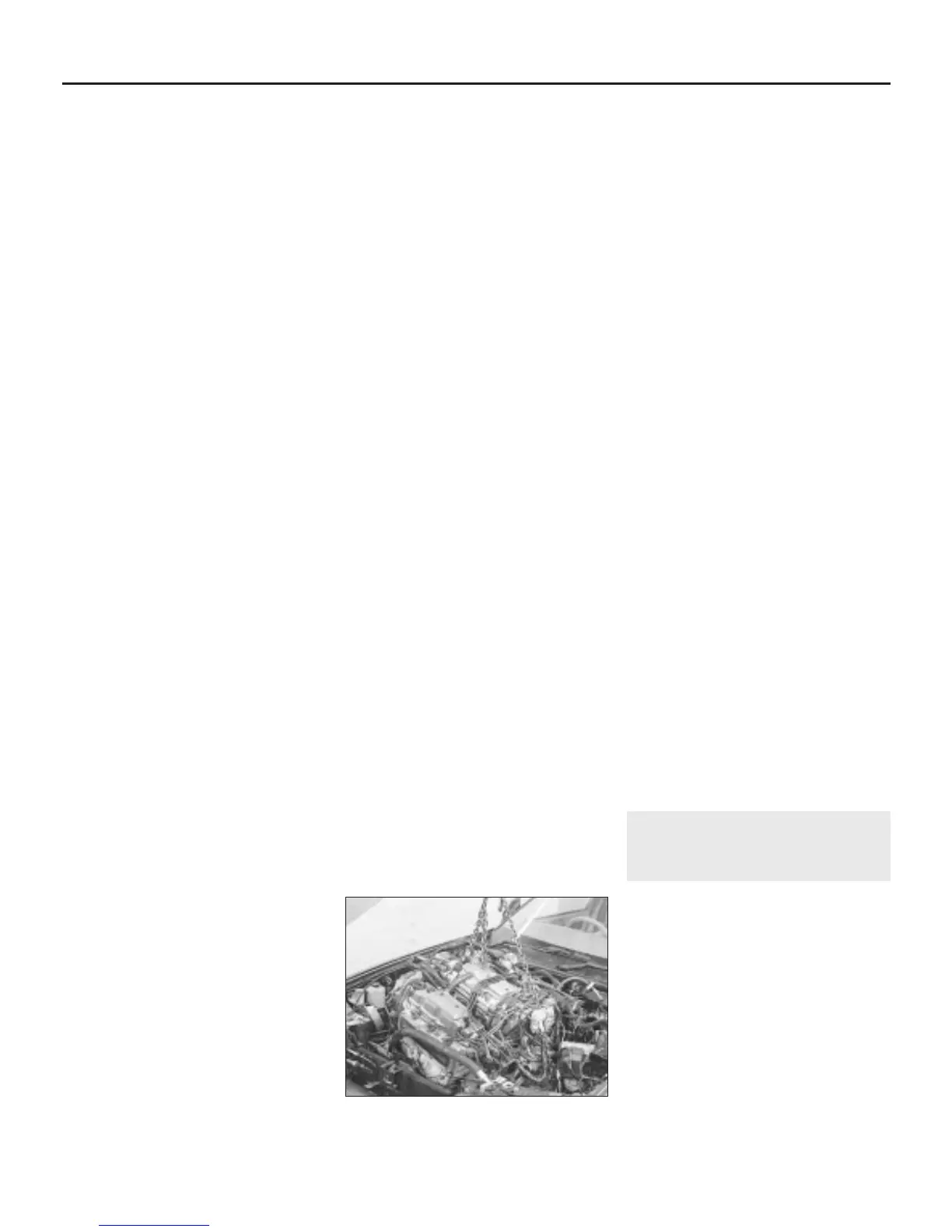
52 Carefully lift the power unit upwards,
whilst moving and twisting it slightly to clear
the various projections (see illustration).
When the unit has been raised sufficiently,
draw the hoist forwards to bring the assembly
over the front body panel, then lower it to the
floor.
Separation - manual
transmission models
53 With the engine/transmission removed
from the car, undo the starter motor retaining
bolts, and remove the unit from the clutch
housing.
54 Undo the bolts and remove the engine
snubber bracket from the transmission
adaptor plate beneath the engine sump.
55 Undo the bolts securing the rear engine
mounting bracket to the transmission, and
remove the bracket.
56 Undo all the remaining bolts securing the
transmission to the engine.
57 With the transmission well supported,
release the locating dowels and draw the unit
squarely away from the engine.
Separation - automatic
transmission models
58 With the engine/transmission removed
from the car, undo the starter motor retaining
bolts and remove the unit from the converter
housing.
59 Refer to Chapter 7, Part B and release the
kickdown cable from the engine.
60 Turn the crankshaft as necessary, using a
socket or spanner on the crankshaft pulley
bolt, until one of the torque converter retaining
bolts becomes accessible through the
opening on the lower face of the torque
converter housing. Undo the bolt, then turn
the crankshaft and remove the remaining
bolts in the same way.
61 Undo the bolts securing the rear engine
mounting bracket to the transmission, and
remove the bracket.
62 Undo the remaining bolts securing the
transmission to the engine.
63 With the transmission well supported,
release the locating dowels and draw the unit
squarely away from the engine. Ensure that
the torque converter stays in place on the
transmission.
Attachment - all models
64 Attachment is the straightforward reversal
of the separation sequence, but where
applicable, tighten all nuts and bolts to the
specified torque (Chapter 2, Part A). On
manual transmission models, smear the
gearbox mainshaft and release bearing face
with molybdenum disulphide grease before
attachment.
Refitting
65 Refitting is a straightforward reversal of
removal, bearing in mind the following points:
(a) Refit all the engine mounting bolts
loosely, then tighten them so as not to
place any under strain. Ensure that the
right-hand mounting bolt is positioned
centrally within the elongated slot in the
body bracket.
(b) Refill the cooling system as described in
Chapter 1.
(c) Refill the transmission as described in
Chapter 1.
(d) Fill the engine with oil as described in
Chapter 1.
(e) Refill and bleed the power steering
system as described in Chapter 10.
(f) Adjust the accelerator cable as described
in Chapter 4, Part D and where
applicable, the automatic transmission
kickdown cable as described in Chapter 7
Part B.
6 Engine overhaul -
dismantling sequence
1 The engine dismantling and reassembly
tasks are made easier if the engine is
mounted on a portable engine stand which
can be hired.
2 If a stand is not available, it is possible to
dismantle the engine with it supported on a
strong workbench or on the floor. Be careful
not to tip or drop the engine when working
without a stand.
3 If a reconditioned engine is to be fitted, all
external components of the original engine
must be removed in order to transfer them to
the replacement unit (as they will if you are
doing a complete engine rebuild). These
components include the following, according
to engine type.
2C•8 Engine removal and general engine overhaul procedures
5.52 Removing the engine and
transmission from the car
1380 Rover 800 Series Remake
 Loading...