12 Piston/connecting rod
assemblies (V6 engine) -
removal
3
The procedure is the same as described in
the previous Section for 4-cylinder engines,
but turn the crankshaft as necessary until
each pair of pistons are at the bottom of their
stroke and their connecting rod caps are
accessible. On later engines it will be
necessary to remove the oil baffle retaining
bolts and remove the baffle for access to the
crankshaft components.
13 Crankshaft (4-cylinder
engine) - removal
3
Note: The crankshaft can be removed only
after the engine has been removed from the
vehicle. It is assumed that the transmission,
flywheel/driveplate, adaptor plate, timing belt,
cylinder head, sump, oil pump pick-
up/strainer, oil pump, and piston/connecting
rod assemblies, have already been removed.
1 Before the crankshaft is removed, check
the endfloat. Mount a DTI (Dial Test Indicator,
or dial gauge) with the stem in line with the
crankshaft and just touching the crankshaft.
2 Push the crankshaft fully away from the
gauge, and zero it. Next, lever the crankshaft
towards the gauge as far as possible, and
check the reading obtained. The distance that
the crankshaft moved is its endfloat; if it is
greater than specified, check the crankshaft
thrust surfaces for wear. If no wear is evident,
new thrustwashers should correct the
endfloat.
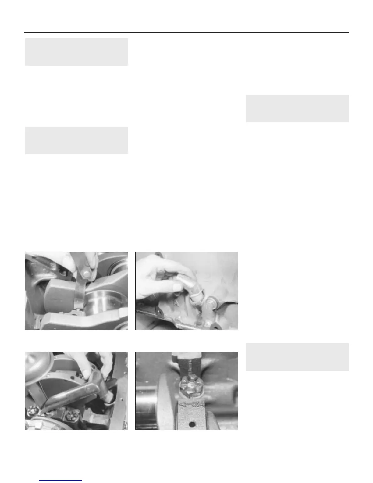
3 Feeler gauges can be used if no dial gauge
is available. Lever or push the crankshaft all
the way towards the right-hand end of the
engine. Slip feeler gauges between the
crankshaft and the main bearing incorporating
the thrustwashers to determine the clearance
(see illustration).
4 Withdraw the crankcase breather tube
elbow from the outside of the cylinder block
(see illustration).
5 From within the crankcase, remove the
crankcase breather extension tube (see
illustration). To do this, move the tube from
side to side to release the sealing compound,
then tap it out using a dowel rod inserted
through the elbow aperture.
6 Note that the main bearing caps have their
numbers cast on the face of each cap, and in
addition, Nos 2, 3 and 4 have arrows
indicating their fitted direction (see
illustration).
7 Undo the main bearing cap retaining bolts,
one turn at a time, then when all are slack,
remove the bolts.
8 Lift away each main bearing cap and the
bottom half of each bearing shell, taking care
to keep the bearing shell with the right cap. If
the caps are tight, tap them on their sides with
a plastic mallet to release them from the
locating dowels.
9 When removing the centre main bearing
cap, note the bottom semi-circular halves of
the thrustwashers, one located on each side
of the cap. Lay them, with the centre bearing
cap, along the correct side.
10 Lift out the crankshaft, followed by the
bearing shell upper halves and the
thrustwashers. Keep the bearing shells and
thrustwashers with their correct caps.
14 Crankshaft (V6 engine) -
removal
3
Note: The crankshaft can be removed only
after the engine has been removed from the
vehicle. It is assumed that the transmission,
flywheel/driveplate, rear oil seal carrier, timing
belt, cylinder head, sump, oil pump pick-
up/strainer, oil pump, and piston/connecting
rod assemblies, have already been removed.
1 Before removing the crankshaft, check the
endfloat as described in the previous Section.
2 Where fitted, undo the bolts and remove
the oil baffle from the bottom of the
crankcase. Undo the eight oil gallery retaining
bolts and lift the oil gallery off the main
bearing caps. Collect the four O-rings from
the base of the gallery (see illustration).
3 Using a hammer and centre punch, mark
the main bearing caps, 1 to 4 and make a
mark to indicate their fitted direction in the
crankcase.
4 Undo the main bearing cap retaining bolts,
two on the bottom and two on the side, one
turn at a time; when all are slack, remove the
bolts.
5 Screw in two oil gallery bolts into each main
bearing cap and pull up on the bolts to
withdraw the caps from their locations (see
illustration). Lift away each main bearing cap
and the bottom half of each bearing shell,
taking care to keep the bearing shell with the
right cap. Remove the oil gallery bolts after
removing the caps.
6 Lift out the crankshaft, followed by the
bearing shell upper halves and the two
thrustwashers from the No 4 journal location.
Keep the bearing shells and thrustwashers
with their correct caps.
15 Cylinder block/crankcase -
cleaning and inspection
3
Note: Always check first what replacement
parts are available before planning any
overhaul operation. A Rover dealer, or a good
engine reconditioning specialist/automotive
parts supplier may be able to suggest
alternatives which will enable you to overcome
the lack of replacement parts.
Cleaning
1 Prior to cleaning, remove all external
components and senders, and any gallery
plugs or caps that may be fitted.
2C•12 Engine removal and general engine overhaul procedures
13.6 Main bearing cap identification
number and direction arrow
13.5 Remove the crankcase breather tube
extension tube
13.4 Withdraw the crankcase breather
tube elbow
13.3 Checking crankshaft endfloat using
feeler gauges
1380 Rover 800 Series Remake
 Loading...