8 Tap the top edge of the ring compressor to
make sure it’s contacting the block around its
entire circumference.
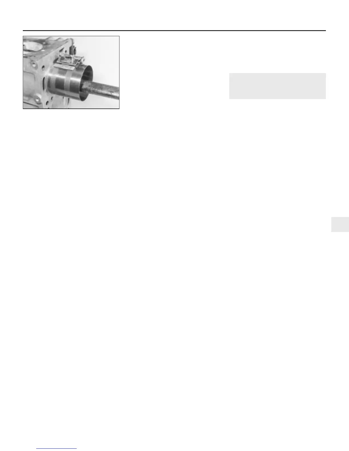
9 Gently tap on the top of the piston with the
end of a wooden hammer handle (see
illustration), while guiding the connecting
rod’s big-end onto the crankpin. The piston
rings may try to pop out of the ring
compressor just before entering the cylinder
bore, so keep some pressure on the ring
compressor. Work slowly, and if any
resistance is felt as the piston enters the
cylinder, stop immediately. Find out what’s
binding, and fix it before proceeding. Do not,
for any reason, force the piston into the
cylinder - you might break a ring and/or the
piston.
10 To check the big-end bearing running
clearance, cut a piece of the appropriate-size
Plastigage slightly shorter than the width of
the connecting rod bearing, and lay it in place
on the No 1 crankpin (big-end) journal, parallel
with the crankshaft centre-line.
11 Clean the connecting rod-to-cap mating
surfaces, and refit the big-end bearing cap.
Tighten the cap bolts to the specified torque
(Chapter 2, Part A). Don’t rotate the
crankshaft at any time during this operation!
12 Unscrew the bolts and detach the cap,
being very careful not to disturb the Plastigage.
13 Compare the width of the crushed
Plastigage to the scale printed on the
Plastigage envelope, to obtain the running
clearance. Compare it to the Specifications,
to make sure the clearance is correct.
14 If the clearance is not as specified, seek
the advice of a Rover dealer or similar engine
reconditioning specialist - if the crankshaft
journals are in good condition, it may be
possible simply to renew the shells to achieve
the correct clearance. If this is not possible,
the crankshaft must be reground by a
specialist, who can also supply the necessary
undersized shells. First though, make sure
that no dirt or oil was trapped between the
bearing shells and the connecting rod or cap
when the clearance was measured. Also,
recheck the crankpin diameter. If the
Plastigage was wider at one end than the
other, the crankpin journal may be tapered.
15 Carefully scrape all traces of the
Plastigage material off the journal and the
bearing surface. Be very careful not to scratch
the bearing - use your fingernail or the edge of
a credit card.
Final piston/connecting rod
refitting
16 Make sure the bearing surfaces are
perfectly clean, then apply a uniform layer of
clean molybdenum disulphide-based grease,
engine assembly lubricant, or clean engine oil,
to both of them. You’ll have to push the piston
into the cylinder to expose the bearing surface
of the shell in the connecting rod.
17 Slide the connecting rod back into place
on the crankpin (big-end) journal, refit the big-
end bearing cap, and then tighten the bolts as
described above.
18 Repeat the entire procedure for the
remaining piston/connecting rod assemblies.
19 The important points to remember are:
(a) Keep the backs of the bearing shells and
the recesses of the connecting rods and
caps perfectly clean when assembling
them.
(b) Make sure you have the correct
piston/rod assembly for each cylinder.
(c) The arrow on the piston crown or the
word FRONT must face the timing belt
end of the engine.
(d) Lubricate the cylinder bores with clean
engine oil.
(e) Lubricate the bearing surfaces when
refitting the big-end bearing caps after the
running clearance has been checked.
20 After all the piston/connecting rod
assemblies have been properly installed,
rotate the crankshaft a number of times by
hand, to check for any obvious binding.
21 Continue with the engine reassembly in
the sequence given in Section 19.
23 Engine -
initial start-up after overhaul
1
1 With the engine refitted in the vehicle,
double-check the engine oil and coolant
levels. Make a final check that everything has
been reconnected, and that there are no tools
or rags left in the engine compartment.
2 Refit the spark plugs, and connect all the
spark plug (HT) leads (Chapter 1). Switch on
the ignition and listen for the fuel pump; it will
run for a little longer than usual, due to the
lack of pressure in the system.
3 Start the engine, noting that this also may
take a little longer than usual, due to the fuel
system components being empty.
4 While the engine is idling, check for fuel,
coolant and oil leaks. Don’t be alarmed if
there are some odd smells and smoke from
parts getting hot and burning off oil deposits.
If the hydraulic tappets have been disturbed,
some valve gear noise may be heard at first;
this should disappear as the oil circulates fully
around the engine, and normal pressure is
restored in the tappets.
5 Keep the engine idling until hot water is felt
circulating through the top hose, check that it
idles reasonably smoothly and at the usual
speed, then switch it off.
6 After a few minutes, recheck the oil and
coolant levels, and top-up as necessary
(Chapter 1).
7 If they were tightened as described, there is
no need to re-tighten the cylinder head bolts
once the engine has first run after reassembly.
8 If new components such as pistons, rings
or crankshaft bearings have been fitted, the
engine must be run-in for the first 500 miles
(800 km). Do not operate the engine at full-
throttle, or allow it to labour in any gear
during this period. It is recommended that the
oil and filter be changed at the end of this
period.
Engine removal and general engine overhaul procedures 2C•19
2C
1380 Rover 800 Series Remake
22.9 Refitting the piston and connecting
rod assemblies, with the aid of a ring
compressor


 To Next Page
 Loading...
