Final refitting
14 Carefully lift the crankshaft out of the
engine. Clean the bearing surfaces of the
shells in the block, then apply a thin, uniform
layer of clean molybdenum disulphide-based
grease, engine assembly lubricant, or clean
engine oil to each surface (see illustration).
Coat the thrustwasher surfaces as well.
15 Lubricate the crankshaft oil seal journals
with molybdenum disulphide-based grease,
engine assembly lubricant, or clean engine oil.
16 Make sure the crankshaft journals are
clean, then lay the crankshaft back in place in
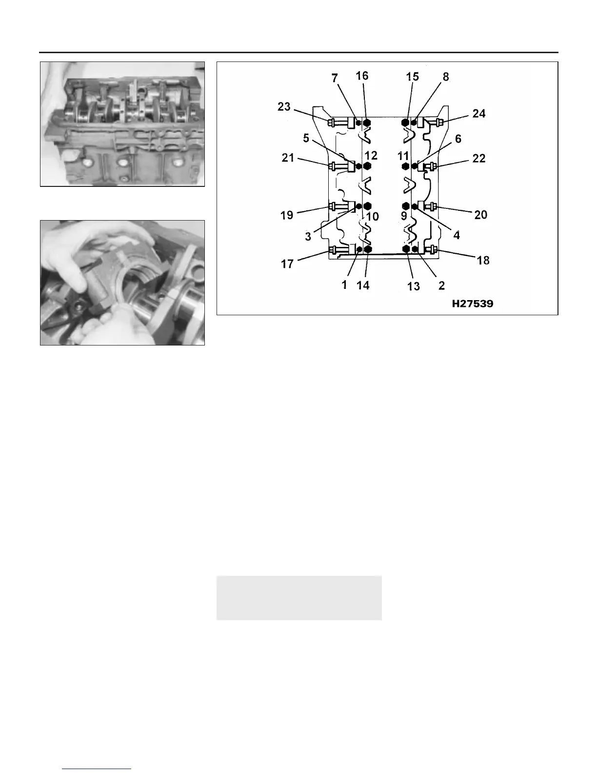
the block (see illustration). Clean the bearing
surfaces of the shells in the caps, then
lubricate them. Install the caps in their
respective positions, with the arrows pointing
to the timing belt end of the engine or the
previously made marks positioned correctly.
When fitting the centre main bearing cap on
4-cylinder engines, ensure that the
thrustwashers, generously lubricated, are
fitted with their oil grooves facing outwards,
and the locating tab of each is engaged with
the slot in the main bearing cap (see
illustration). Apply RTV sealant into the
vertical grooves on the edges of Nos 1 and 5
main bearing caps, then fit these caps to their
locations.
17 On 4-cylinder engines, working on one
cap at a time, from the centre main bearing
outwards (and ensuring that each cap is
tightened down squarely and evenly onto the
block), tighten the main bearing cap bolts to
the specified torque wrench setting (Chap-
ter 2, Part A).
18 On V6 engines, tighten the bolts to the
specified torque (Chapter 2, Part A) in the
sequence shown (see illustration).
19 Rotate the crankshaft a number of times
by hand, to check for any obvious binding.
20 Check the crankshaft endfloat. It should
be correct if the crankshaft thrust faces aren’t
worn or damaged.
21 On 4-cylinder engines, apply sealer to the
crankcase breather tube extension, then fit
the tube to its location. Apply sealant to the
breather tube elbow, and fit the elbow,
ensuring that it is tapped down until the
shoulder contacts the crankcase.
22 On V6 engines, refit the oil gallery, use
new O-ring seals and secure with the bolts
tightened to the specified torque (Chapter 2,
Part A).
23 Refit the engine oil seal carrier, or adaptor
plate and install a new seal (see Part A or B of
this Chapter according to engine type).
22 Piston/connecting rod
assemblies - refitting and big-end
bearing running clearance check
4
1 Before refitting the piston/connecting rod
assemblies, the cylinder bores must be
perfectly clean, the top edge of each cylinder
must be chamfered, and the crankshaft must
be in place.
2 Remove the big-end bearing cap from No 1
cylinder connecting rod (refer to the marks
noted or made on removal). Remove the
original bearing shells, and wipe the bearing
recesses of the connecting rod and cap with a
clean, lint-free cloth. They must be kept
spotlessly-clean!
Big-end bearing running
clearance check
3 Clean the back of the new upper bearing
shell, fit it to the connecting rod, then fit the
other shell of the bearing set to the big-end
bearing cap. Make sure the tab on each shell
fits into the notch in the rod or cap recess.
Caution: Don’t hammer the shells into
place, and don’t nick or gouge the bearing
face. Don’t lubricate the bearing at this
time.
4 It’s critically important that all mating
surfaces of the bearing components are
perfectly clean and oil-free when they’re
assembled.
5 Position the piston ring gaps as described
in Section 16, lubricate the piston and rings
with clean engine oil, and attach a piston ring
compressor to the piston. Leave the skirt
protruding about a quarter-inch, to guide the
piston into the cylinder bore. The rings must
be compressed until they’re flush with the
piston.
6 Rotate the crankshaft until No 1 crankpin
(big-end) journal is at Bottom Dead Centre,
and apply a coat of engine oil to the cylinder
walls.
7 Arrange the No 1 piston/connecting rod
assembly so that the word FRONT or the
arrow on the piston crown points to the timing
belt end of the engine. Gently insert the
assembly into the No 1 cylinder bore, and rest
the bottom edge of the ring compressor on
the engine block.
2C•18 Engine removal and general engine overhaul procedures
21.18 Main bearing cap retaining bolt tightening sequence on V6 engines
21.16b Fitting the crankshaft thrustwasher
lower halves to the centre bearing cap on
4-cylinder engines
21.16a Crankshaft installation
1380 Rover 800 Series Remake


 To Next Page
 Loading...
