the piston. Position the gaps of the two oil
control rails and the expander at 90º to
each other.
4-cylinder “T” series engines - set the
compression ring gaps at 120º to each
other and away from the inlet valve cut-
out side of the piston. Position the gaps
of the two oil control rails at 120º to each
other and the gap of the expander at 120º
to the rail gaps. On turbocharged engines,
position the oil control rail gap and spring
gap at 30º on opposite sides of the
gudgeon pin axis.
V6 engines - set the compression ring gaps at
90º to each other and the oil control
expander gap at 90º to the top ring gap.
Position the oil control rail gaps at 15º
either side of the expander gap.
21 Crankshaft - refitting and
main bearing running
clearance check
4
1 It is assumed at this point that the cylinder
block/crankcase and crankshaft have been
cleaned, inspected and repaired or
reconditioned as necessary. Position the
engine upside-down.
2 Remove the main bearing cap bolts, and lift
out the caps. Lay the caps out in the proper
order, to ensure correct installation.
3 If they’re still in place, remove the old
bearing shells from the block and the main
bearing caps. Wipe the bearing recesses of
the block and caps with a clean, lint-free
cloth. They must be kept spotlessly-clean!
Main bearing running clearance
check
4 Wipe clean the main bearing shell seats in
the crankcase and clean the backs of the
bearing shells. Insert the respective upper
shells (dry) into position in the crankcase and
the lower shells into their respective caps. On
the V6 engines, the shells with the oil groves
are fitted to the crankcase, and the plain
shells are fitted to the caps. Where the old
main bearings are being refitted, ensure that
they are located in their original positions.
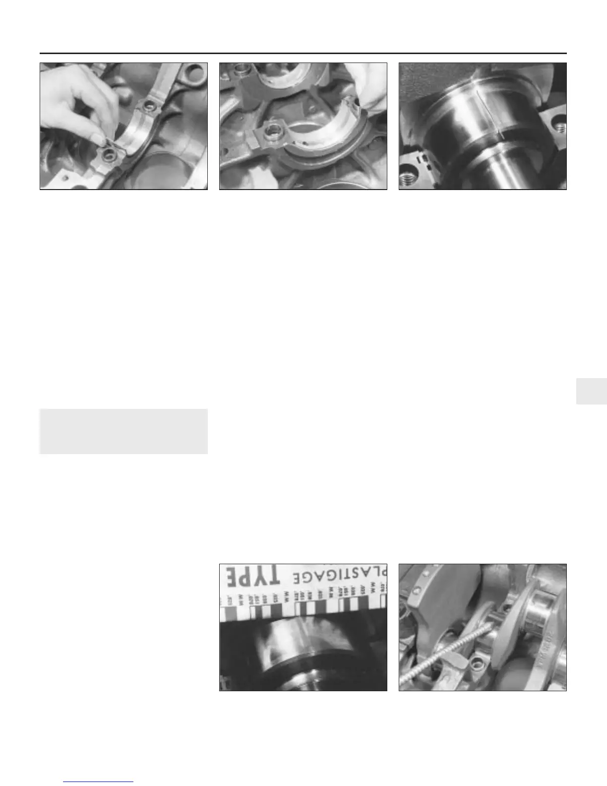
Make sure the tab on each bearing shell fits
into the notch in the block or cap (see
illustration).
Caution: Don’t hammer the shells into
place, and don’t nick or gouge the bearing
faces. No lubrication should be used at
this time.
5 Place the crankshaft thrustwashers into
position in the crankcase so that their oil
grooves are facing outwards (away from the
central web) (see illustration).
6 Clean the bearing surfaces of the shells in
the block, and the crankshaft main bearing
journals with a clean, lint-free cloth. Check or
clean the oil holes in the crankshaft, as any
dirt here can go only one way - straight
through the new bearings.
7 Once you’re certain the crankshaft is clean,
carefully lay it in position in the main bearings.
Trim several pieces of the appropriate-size
Plastigage (they must be slightly shorter than
the width of the main bearings), and place one
piece on each crankshaft main bearing
journal, parallel with the crankshaft centre-line
(see illustration).
8 Clean the bearing surfaces of the cap
shells, and install the caps in their respective
positions (don’t mix them up) with the arrows
pointing to the timing belt end of the engine or
positioned according to the marks made
during removal. Don’t disturb the Plastigage.
9 Working on one cap at a time, from the
centre main bearing outwards (and ensuring
that each cap is tightened down squarely and
evenly onto the block), tighten the main
bearing cap bolts to the specified torque
wrench setting (Chapter 2, Part A). Don’t
rotate the crankshaft at any time during this
operation!
10 Remove the bolts, and carefully lift off the
main bearing caps (on V6 engines, use the oil
gallery bolts as before). Keep them in order.
Don’t disturb the Plastigage or rotate the
crankshaft.
11 Compare the width of the crushed
Plastigage on each journal with the scale
printed on the Plastigage envelope to obtain
the main bearing running clearance (see
illustration). Check the Specifications to
make sure that the clearance is correct.
12 If the clearance is not as specified, seek
the advice of a Rover dealer or similar engine
reconditioning specialist - if the crankshaft
journals are in good condition, it may be
possible simply to renew the shells to achieve
the correct clearance. If this is not possible,
the crankshaft must be reground by a
specialist who can supply the necessary
undersized shells. First though, make sure
that no dirt or oil was between the bearing
shells and the caps or block when the
clearance was measured. If the Plastigage is
noticeably wider at one end than the other,
the journal may be tapered.
13 Carefully scrape all traces of the
Plastigage material off the main bearing
journals and the bearing surfaces. Be very
careful not to scratch the bearing - use your
fingernail or the edge of a credit card.
Engine removal and general engine overhaul procedures 2C•17
21.7 Plastigage in place on a crankshaft
main bearing journal
21.5 Fitting the crankshaft thrustwashers21.4 Fitting the main bearing shell upper
halves
21.14 Thoroughly lubricate the crankshaft
journals
21.11 Measuring the width of the
deformed Plastigage using the scale on
the card provided
2C
1380 Rover 800 Series Remake


 To Next Page
 Loading...
