1 General information
Engine cooling system
The cooling system is of the pressurized,
pump-assisted thermosyphon type. The
system consists of the radiator, water pump,
thermostat, electric cooling fan, expansion
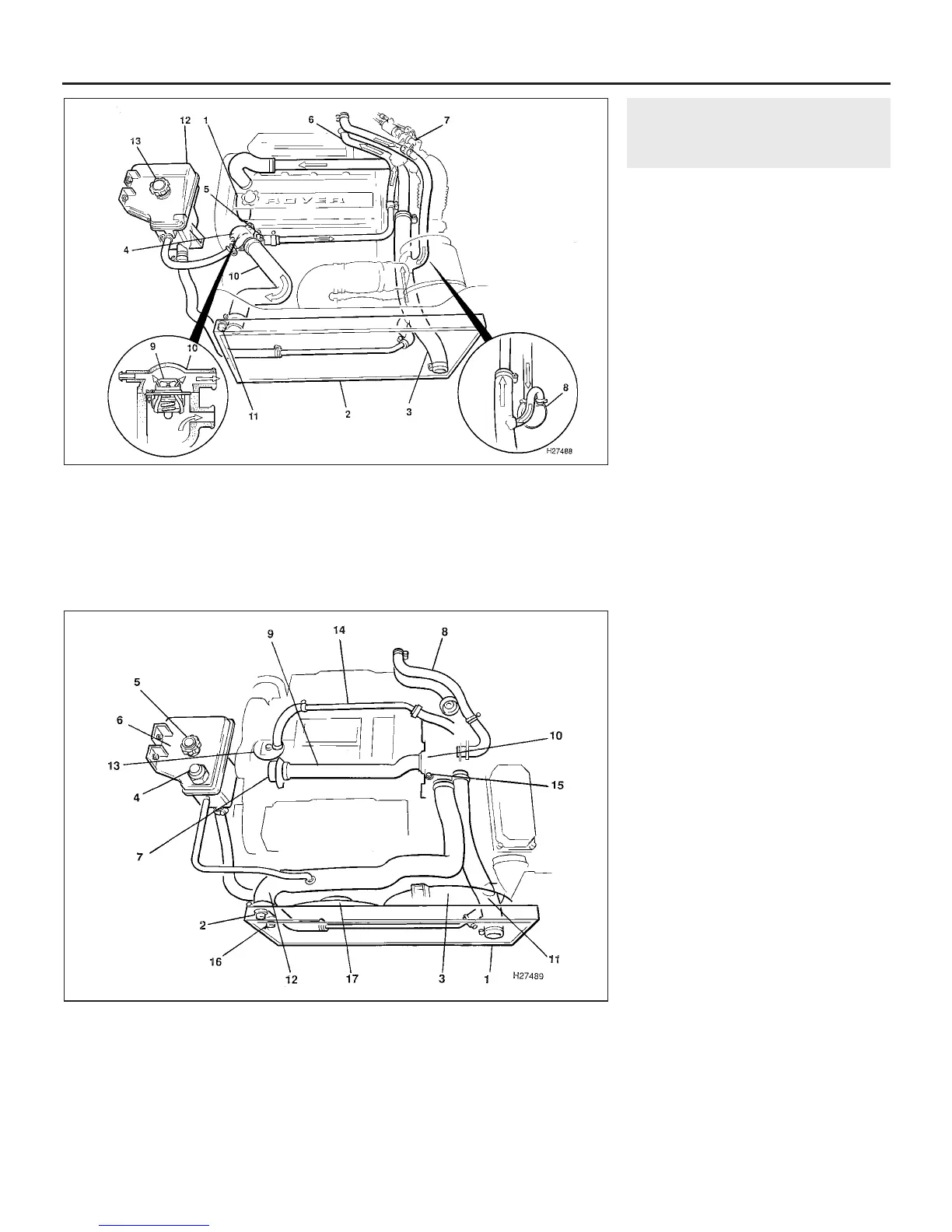
tank and associated hoses (see illustrations).
On “M” series 4-cylinder engines, and V6
engines, the impeller type water pump is
mounted on the right-hand end of the engine,
and is driven by the timing belt. On “T” series
4-cylinder engines, the water pump is
mounted behind, and driven by, the power
steering pump, which itself is driven by the
auxiliary drive belt.
The system functions as follows. Cold
coolant in the bottom of the radiator left-hand
tank passes, via hoses and pipes, to the water
pump, where it is pumped around the cylinder
block and head passages. After cooling the
cylinder bores, combustion surfaces and valve
seats, the coolant reaches the underside of the
thermostat, which is initially closed, and is
diverted through a bypass hose to the heater
matrix. On 4-cylinder engines, after passing
through the heater, the coolant travels through
the water jacket of the inlet manifold or throttle
housing, and to the turbocharger, or to the
automatic transmission fluid cooler where
applicable, before returning to the water pump
inlet hose. On V6 engines, after passing
through the heater, the coolant circulates
through the engine oil cooler, fuel system fast
idle valve, idle control valve, throttle body and
inlet manifold and to the automatic
transmission fluid cooler, where applicable,
before returning to the water pump.
When the engine is cold, the thermostat
remains closed, and the coolant only
circulates as described. When the coolant
reaches a predetermined temperature, the
thermostat opens, and the coolant passes
through the top hose to the radiator right-
hand tank. As the coolant circulates around
the radiator, it is cooled by the inrush of air
when the car is in forward motion. Airflow is
supplemented by the action of the electric
cooling fan(s) when necessary. Upon reaching
the left-hand side of the radiator, the coolant
is now cooled and the cycle is repeated.
When the engine is at normal operating
temperature, the coolant expands, and some
of it is displaced into the expansion tank. This
coolant collects in the tank, and is returned to
the radiator when the system cools.
The electric cooling fan mounted on the
radiator is controlled by a thermostatic switch,
located in the radiator right-hand side tank. At
a predetermined coolant temperature, the
switch contacts close, thus actuating the fan.
On models equipped with air conditioning,
additional fans are fitted for cooling of the air
conditioning system condenser.
3•2 Cooling, heating and air conditioning systems
1.1a Cooling system layout and flow diagram - 4-cylinder engines
1.1b Cooling system layout - V6 engines
Dark arrows indicate hot
coolant flow
Light arrows indicate cold
coolant flow
1 Water pump
2 Radiator
3 Bottom hose
4 Thermostat housing
5 Bypass (heater) hose
6 Heater hose
7 Throttle housing
8 Automatic transmission
fluid cooler
9 Thermostat open
10 Coolant flow through top
hose
11 Cooling fan thermostatic
switch
12 Expansion tank
13 Pressure cap
1 Radiator
2 Cooling fan thermostatic
switch
3 Radiator cooling fan
4 Coolant low level switch
5 Pressure cap
6 Expansion tank
7 Water pump
8 Heater hoses
9 Water pump inlet pipe
10 Thermostat housing
11 Bottom hose
12 Top hose
13 Oil cooler
14 Oil cooler return pipe
15 Bleed screw
16 Air conditioning condenser
fan thermostatic switch
17 Air conditioning condenser
fan
1380 Rover 800 Series Remake


 To Next Page
 Loading...
