12 Heater/air conditioning
controls -
removal and refitting
1
Heater control unit and cables
Removal
1 Remove the cowl around the instrument
panel as described in Chapter 12, Section 9.
2 Remove the trim panel under the facia on
the driver’s side.
3 Extract the outer cable retaining clips, and
slip the cable ends off the heater levers.
4 Withdraw the control unit and cables from
the facia.
5 Release the two inner and outer cables
from the control unit.
Refitting
6 Refitting is a reversal of removal. When
connecting the heater cables, adjust the
position of the outer cables in their retaining
clips so as to give full travel of the heater
levers, consistent with full travel of the control
levers.
Air conditioning control unit
7 Refer to “Instrument cowl switch units” in
Chapter 12, Section 4.
13 Air conditioning system -
general information and
precautions
General information
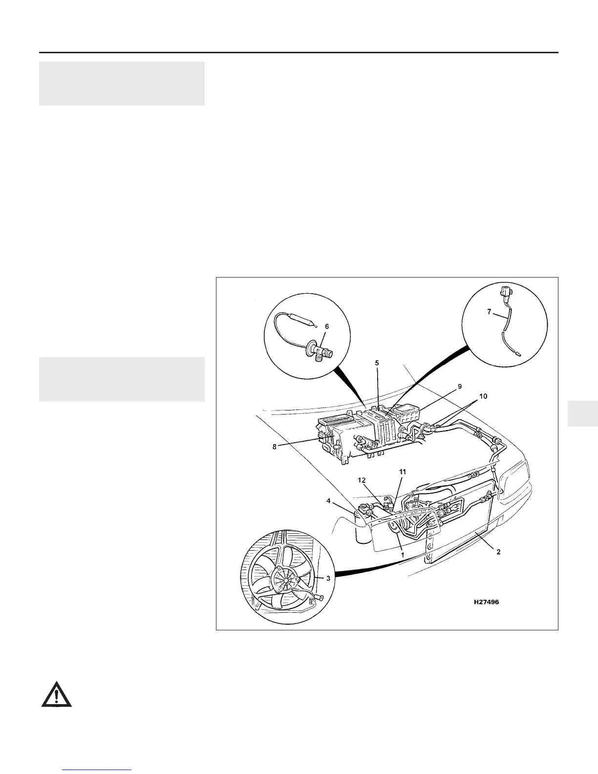
The air conditioning system consists of a
condenser mounted in front of the radiator, an
evaporator mounted adjacent to the heater
matrix, a compressor mounted on the engine,
a receiver/dryer, and the plumbing connecting
all of the above components (see
illustration).
A blower fan forces the warmer air of the
passenger compartment through the
evaporator core (rather like a radiator in
reverse), transferring the heat from the air to
the refrigerant. The liquid refrigerant boils off
into low-pressure vapour, taking the heat with
it when it leaves the evaporator.
Two versions of the system are used, the
change point being on models from
VIN 152206 onwards. Both versions are
virtually identical in component layout apart
from minor differences in the condenser pipe
connections. The main difference, however is
that the later version uses the more
environmentally friendly R134a refrigerant
whereas the early version uses the ozone-
depleting R12.
Precautions
Warning: The air conditioning
system is under high pressure.
Do not loosen any fittings or
remove any components until
after the system has been discharged. Air
conditioning refrigerant should be properly
discharged into an approved type of
container, at a dealer service department
or an automotive air conditioning repair
facility capable of handling the refrigerant
safely. Always wear eye protection when
disconnecting air conditioning system
fittings.
When an air conditioning system is fitted, it
is necessary to observe the following special
precautions whenever dealing with any part of
the system, its associated components, and
any items which necessitate disconnection of
the system:
(a) While the refrigerant used on later models
- R134a - is less damaging to the
environment than the previously-used
R12, both are very dangerous substances.
They must not be allowed into contact
with the skin or eyes, or there is a risk of
frostbite. They must also not be
discharged in an enclosed space as there
is a risk of suffocation. The refrigerant is
heavier than air, and so must never be
discharged over a pit.
(b) The refrigerant must not be allowed to
come in contact with a naked flame,
otherwise a poisonous gas will be created
- under certain circumstances, this can
form an explosive mixture with air. For
similar reasons, smoking in the presence
of refrigerant is highly dangerous,
particularly if the vapour is inhaled
through a lighted cigarette.
(c) Never discharge the system to the
atmosphere - R134a is not an ozone-
depleting ChloroFluoroCarbon (CFC) as is
R12, but is instead a hydrofluorocarbon,
which causes environmental damage by
contributing to the “greenhouse effect” if
released into the atmosphere.
(d) R134a refrigerant must not be mixed with
R12; the system uses different seals and
Cooling, heating and air conditioning systems 3•11
13.1 Air conditioning system layout (V6 engine installation shown - 4-cylinder engine
installation similar)
1 Compressor
2 Condenser
3 Cooling fans (behind
radiator)
4 Receiver/drier
5 Evaporator
6 Thermostatic expansion
valve
7 Thermistor
8 Heater distribution and
blend unit
9 Blower unit
10 High and low pressure
servicing connections
11 High pressure switch
12 Dual pressure switch
3
1380 Rover 800 Series Remake


 To Next Page
 Loading...
