TRIMMING LINE INSTALLATION
This section covers both SplitLine® and standard single line installation.
Always use original equipment manufacturer 0.095 in. (2.41 mm) replacement line. Line other than the
specified may make the engine overheat or fail.
There are two methods to replace the trimming line:
• Wind the inner reel with new line
• Install a prewound inner reel
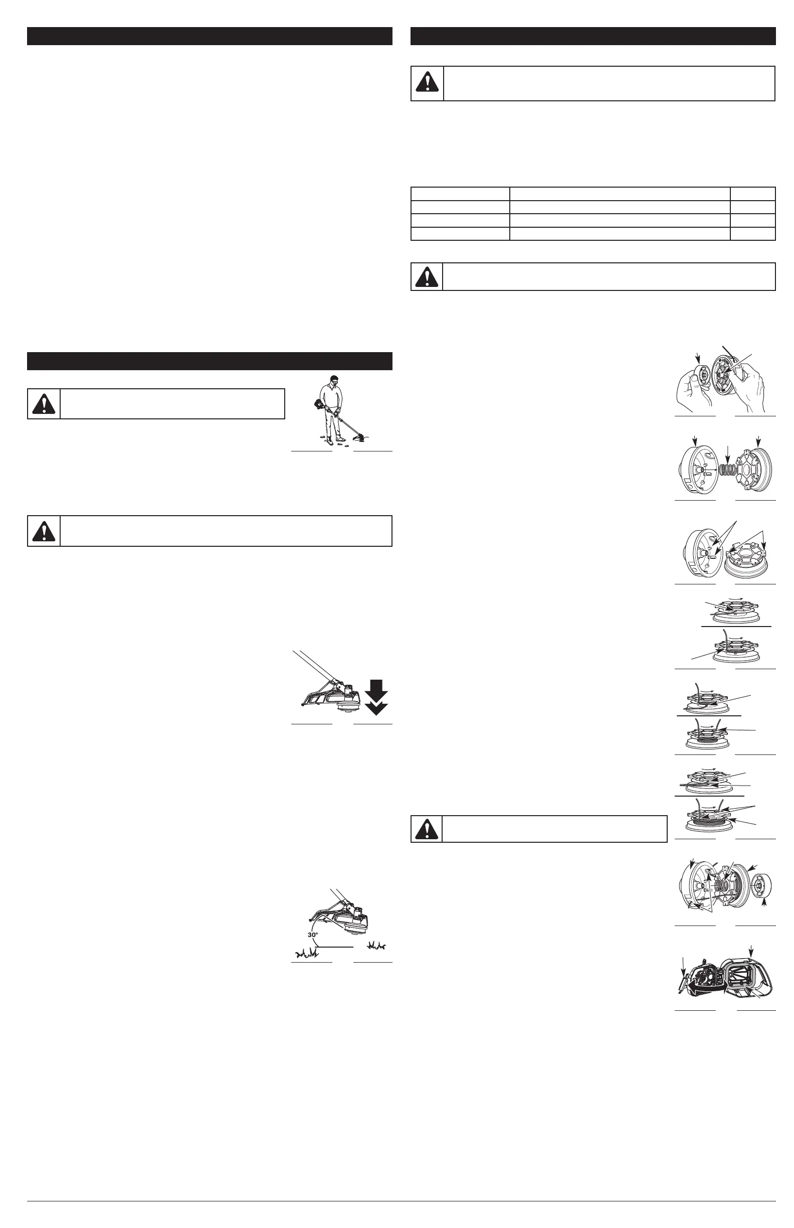
Removing the Existing Inner Reel
1. Hold the outer spool with one hand and unscrew the bump knob
counterclockwise (Fig. 12). Inspect the bolt inside the bump knob to
make sure it moves freely. Replace the bump knob if damaged.
2. Remove the inner reel from the outer spool (Fig. 13).
3. Remove spring from the inner reel (Fig. 13).
4. Use a clean cloth to clean the inner reel, spring, shaft and inner
surface of the outer spool.
5. Check the indexing teeth on the inner reel and slots on outer spool for
wear (Fig. 14). If necessary, remove burrs or replace the reel and spool.
NOTE: Always use the correct line length when installing trimming line on
the unit. The line may not release properly if the line is too long.
Single Line Installation
Go To Step 8 for SplitLine® Installation:
6. Cut approximately two 8 feet lengths (2.4 m) of new single trimming
line. Insert end of line into top hole (Fig. 15). Wind tightly in direction
shown on the bottom of the inner reel until about 6 inches (150 mm)
of line remains. Insert end of line into nearest .095 slot (Fig. 15).
7. Insert other end of line into bottom hole (Fig. 16). Wind this line tightly
in the direction shown on the bottom of the inner reel until about 3 to
9 inches (75 to 225 mm) of line remains and insert into opposite .095
slot (Fig. 16). Go to Step 12.
SplitLine® Installation
8. Take approximately 6 feet (1.8 m) of new SplitLine® trimming line.
Split each end about 6 inches (150 mm) (Fig. 17).
9. Insert each end of the line into one hole on either side of split wall
(Fig. 17).
10. Wind tightly in direction indicated on the inner reel. Split wall will
divide the line as you wind. Wind until line is completely divided.
NOTE: Failure to wind the line in the direction indicated will cause the
cutting head to operate incorrectly.
11. Insert the ends of the line into the two .095 holding slots (Fig. 17). Go
to Step 12.
Wound or Pre-Wound Reel Installation
12. Insert or slide the ends of the line through or into the eyelets in the
outer spool and place inner reel with spring inside the outer spool
(Fig. 18). Push the inner reel and outer spool together.
NOTE: The spring must be assembled on the inner reel before
reassembling the cutting head.
13. While holding the inner reel and outer spool, grasp the ends and pull
firmly to release the line from the holding slots in the spool.
14. Hold the inner reel in place and install the bump knob by turning
clockwise. Tighten securely.
AIR FILTER MAINTENANCE
Cleaning the Air Filter
Failure to maintain the air filter properly can result in poor performance or
can cause permanent damage to the engine.
1. Open the air filter cover by pressing the lock tab in and pulling out on
the air filter cover (Fig. 19).
2. Remove the air filter (Fig. 19).
3. Wash the filter in detergent and water. Rinse the filter thoroughly and
allow it to dry.
4. Apply enough clean SAE 30 motor oil to lightly coat the filter.
5. Squeeze the filter to spread and remove excess oil.
6. Replace the air filter into the air filter cover (Fig. 19).
NOTE: Operating the unit without the air filter WILL VOID the warranty.
7. Close the air filter cover by swinging it to the left and then pressing it
down until the lock tab snaps into place (Fig. 19).
Fig. 15
Fig. 16
Fig. 17
Indexing Teeth
Fig. 14
Spring
Fig. 18
Eyelets
Bolt
Bump Knob
Fig. 12
4
WARNING: To avoid serious personal injury, always turn
the unit off and allow it to cool before cleaning or servicing it.
WARNING: Never use metal-reinforced line, wire, chain or rope. These can break off and
become dangerous projectiles.
Outer Spool
Spring
Inner Reel
Fig. 13
MAINTENANCE SCHEDULE
Perform these required maintenance procedures at the frequency stated in the table. These
procedures should also be a part of any seasonal tune-up.
NOTE: Some maintenance procedures may require special tools or skills. If you are unsure about
these procedures take your unit to any non-road engine repair establishment, individual or
authorized service dealer.
NOTE: Maintenance, replacement, or repair of the emission control devices and system may be
performed by any non-road engine repair establishment, individual or authorized service dealer.
WARNING: To prevent serious injury, never perform maintenance or repairs with unit
running. Always service and repair a cool unit. Disconnect the spark plug wire to ensure
that the unit cannot start.
MAINTENANCE
FREQUENCY MAINTENANCE REQUIRED SEE
Before starting the engine Fill the fuel tank with fresh fuel p. 3
Every 10 hours Clean and re-oil the air filter p. 4
Every 25 hours Check the spark plug condition and gap p. 5
OPERATION
HOLDING THE UNIT
Before operating the unit, stand in the operating position (Fig. 9). Check
for the following:
• The operator is wearing eye protection and proper clothing
• With a slightly-bent right arm, the operator’s hand is holding the shaft grip
• The operator’s left arm is straight, the left hand holding the D-handle
• The unit is at waist level
• The cutting head is parallel to the ground and easily contacts the grass without the need to bend over
ADJUSTING TRIMMING LINE LENGTH
The Bump Head™ cutting head allows the release of trimming line without stopping the engine. To release
more line, lightly tap the cutting head on the ground (Fig. 10) while operating the unit at high speed.
NOTE: Always keep the trimming line fully extended. Line release becomes more difficult when the
cutting line gets shorter.
Each time the head is bumped, about 1 inch (25.4 mm) of trimming line releases. A blade in the
cutting head shield will cut the line to the proper length if any excess line is released.
For best results, tap the bump knob on bare ground or hard soil. If attempting a line release in tall
grass, the engine may stall.
NOTE: Do not rest the Bump Head™ on the ground while the unit is running.
Some line breakage will occur from:
• Entanglement with foreign matter
• Normal line fatigue
• Attempting to cut thick, stalky weeds
• Forcing the line into objects such as walls or fence posts
TIPS FOR BEST TRIMMING RESULTS
• Keep the cutting head parallel to the ground.
• Do not force the cutting head. Allow the tip of the line to do the
cutting, especially along walls. Cutting with more than the tip will reduce cutting efficiency and
may overload the engine.
• Cut grass over 8 inches (200 mm) by working from top to bottom in small increments to avoid
premature line wear or engine drag.
• Cut from right to left whenever possible. Cutting to the left improves the unit's cutting efficiency.
Clippings are thrown away from the operator.
• Slowly move the unit into and out of the cutting area at the desired height. Move either in a
forward-backward or side-to-side motion. Cutting shorter lengths produces the best results.
• Trim only when grass and weeds are dry.
• The life of the cutting line is dependent upon:
• Following the trimming techniques
• What vegetation is being cut
• Where vegetation is cut
For example, the line will wear faster when trimming against a foundation wall as opposed to
trimming around a tree.
DECORATIVE TRIMMING
Decorative trimming is accomplished by removing all vegetation around
trees, posts, fences, etc.
Rotate the whole unit so that the cutting head is at a 30° angle to the
ground (Fig. 11).
WARNING: Always wear eye, hearing, foot and body
protection to reduce the risk of injury when operating this unit.
Fig. 9
Fig. 10
Fig. 11
WARNING: Do not remove or alter the line cutting blade assembly. Excessive line length
will cause premature engine failure and / or unit damage.
Slots (4)
Top Hole
Slot
Bottom
Hole
Slot
Top Hole
Bottom
Hole
Slots
Split
Wall
Bump
Knob
Outer Spool
Inner
Reel
STARTING AND STOPPING
2. Fill the fuel tank with fresh fuel mix. Refer to Fueling the Unit.
NOTE: There is no need to turn the unit on. The On/Off Control is in the ON ( I ) position at all times (Fig. 6).
3. Fully press and release the primer bulb 10 times, slowly. Some amount of fuel should be visible in the
primer bulb (Fig. 7). If fuel can not be seen in the bulb, press and release the bulb until fuel is visible.
4. Move the choke lever to Position 1 (Fig. 7).
5. Crouch in the starting position (Fig. 8). Place the Power Start Bit
TM
into the back of the unit (Fig.
22). Refer to the Operation section of the Power Start Bit
TM
operator’s manual.
6. Squeeze the throttle control lever. Press and hold the drill ON (I) button for 2 seconds.
7. Move the choke lever to Position 2 (Fig. 7)
8. Squeeze the throttle control lever, press and hold the drill ON (I) button for 2-second intervals until the
unit starts.
9. Continue to squeeze the throttle control, remove the Power Start Bit
TM
from the unit and allow the
engine to warm up for 30 to 60 seconds.
10. Continue squeezing the throttle control, move the choke lever to Position 3 (Fig. 7) and continue
warming the engine for an additional 60 seconds. The unit may be used during this time.
NOTE: The unit is properly warmed up when the engine accelerates without hesitation.
IF... the engine hesitates, return the choke lever to Position 2 (Fig. 7) and continue the warm-up.
IF... the engine does not start, go back to step 3.
IF... the engine fails to start after a few attempts, move the choke lever to Position 3 and squeeze the
throttle control. Press and hold the drill ON (I) button for 2-second intervals until the unit starts.
IF WARM... If the engine is already warm, go back to step 7
STOPPING INSTRUCTIONS
1. Release the throttle control and allow the engine to cool down by idling.
2. Press and hold the On/Off Control switch in the OFF (O) position until the unit comes to a
complete stop (Fig. 6).
Fig. 19
Air Filter Cover
Air Filter
Lock
Tab
 Loading...