22. Reinstall the modified Coin Dispenser Assembly and secure it with the 3/8” bolt.
23. Reinstall the coin chute with the two ¼” screws.
24. Connect the new Coin Dispenser Assembly harness to header C2A of the new board.
Run the harness up through the left rear hole and connect it to the Coin Dispenser
Assembly.
25. Mount the hopper into the Coin Dispenser Assembly and set it back into position.
26. Connect the two terminals of the empty lamp harness to the bulb on the front door;
polarity is not important. Run the harness down along the hinge of the door identically
to the original harness. Route the harness along the right hand wall of the changer and
then attached to header P5 of the control board.
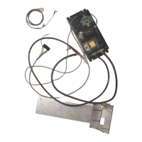
27. Mount the validator to the metal slide plate using three of the four 11/32” nuts provided
with the Mars validator.
28. Connect the validator harness to the validator. Attach the green and yellow wires to the
stud post on the slide plate that did not have a bolt attached to it in the above step.
The validator is now secured to the slide plate with all four nuts.
29. Slide the validator slide plate assembly down the tracks that originally held the
transport.
30. Connect the harness from the validator to header P7 of the control board.
31. Confirm that the harnesses are connected to headers P3, P4, P5, P6, and P7. Headers
P1 and P2 are used when the board is installed in a SBC2/SBC4 and not used in this
application.
32. Dump enough coins into the hopper to cover the low coins screw and make contact with
the metal of the hopper.
33. Plug the power cord into a wall outlet to restore power to the changer. If the red +5vdc
power LED on the board does not light the on/off switch of the new power input cord is
in the off position.
34. If the installation has been done properly the mode LED will light.
35. If the mode LED is not lit depress the reset button.
36. Insert a bill into the validator to confirm the update is working properly. When the
board is shipped, dipswitch 3 is in the “on” position so four coins are paid out for each
dollar value. The payouts are programmed as shown below:
Switch 1 “on” pays out 1 coin
Switch 2 “on” pays out 2 coins
Switch 3 “on” pays out 4 coins
Switch 4 “on” pays out 8 coins
Installation Instructions for Hopper “Low Coins” Screw
(Rowe BC1, SBC2/4 and BC100 Changers)
Upon verifying the kit and changer are working properly, a low coins screw can be installed.
The low coins screw is installed to prevent shortchanging a customer. If the changer is in
an attended location and the hopper will not empty, it is not necessary to install the low
coins screws. The bypass jumper is installed on header P7 when the kits are shipped.
The screw is used to detect ground through the coins in the hopper. When the coins are not
touching the screw and metal wall of the hopper, the changer will no longer accept bills.
The reset button on the control board must be depressed after the hopper has been filled to
reset the board.
Installation Instructions
1. Turn off the changer.
2. Remove the hopper form the changer and set it in a work area. If it is filled with coins,
remove the coins.
 Loading...