3. Drill an 11/64” hole in the black plastic area at the bottom of the hopper. The hole should
be located at the center of the hopper and 7/8” from the very bottom of the plastic.
Positioning is important so that a coin does not get wedged between the screw and the
hopper body.
4. Insert a screw through the hole. Reach your hand into the hopper and align the nut. Begin
tightening the screw while holding the nut. When the nut is almost fully tightened, slip the
open spade terminal under the screw head. Finish tightening the screw so the harness is
held securely in place. The terminal should be positioned so that it is vertical; 3:00 or
9:00.
5. Place the second fork terminal under one of the ¼” hex screws near the black plastic area.
6. Place the hopper back in the changer.
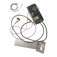
7. Run the harness over the control board. Unplug the bypass Jumper at P7 and attach the
new harness.
8. Secure the harness neatly in the changer using the tie mounts supplied in the parts kit.
9. Refill the hopper with coins so the screw is covered.
10. Turn on the changer. After a 10-second warm-up period, the validator will accept bills.
11. Place the label on hopper that warns service personnel not to remove hopper without
disconnecting the empty sensor wire
TROUBLESHOOTING TIPS
The status LED on the control board will display the following codes:
1 Blink – Hopper is empty or has no continuity from harness to control board
2 Blinks – Time out feature; the maximum allowed time of 20 seconds between coin counts
was exceeded
3 Blinks – Over payment of coins
4 Blinks – The red LED count emitter is bad or is covered – the counting collector (across
from emitter) may be bad.
5 Blinks – The dipswitches are not set, thus no payout is possible
If the +5vdc LED on the board is not lit check the following:
1. Wall outlet has power and the machines power cord is in excellent condition.
2. The on/off switch on the power input line is in the “on” position.
3. Unplug the machine and confirm that fuse #1 on the control board is good. It is a
2 amp fuse; 20mm.
The input button on the control board can be used to simulate pulses from a dollar bill
validator to test the board. This button must be pressed rapidly. It must be presses once,
twice, five, ten, or twenty times as the board will shut down if an impossible dollar value is
entered. The pulses must be inputted quickly. If the board shuts down depress the reset
button.
 Loading...