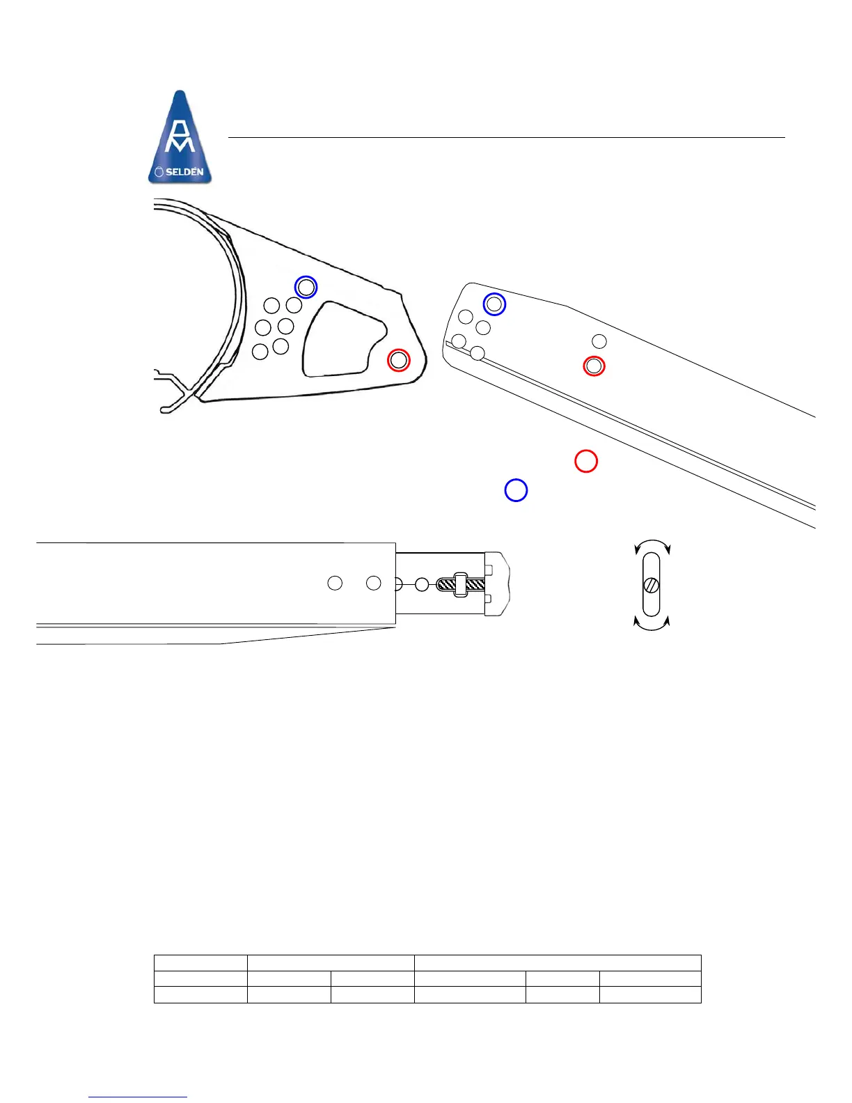
Laser 2000 Spreader Instructions
Primary Pin:
Fit down throug
Adjuster Pin:
Fit down through
Spreader End Ca
The spreader end ca
sizes are identified on the front face of the end cap (See diagram above). To find which wire slot you
require for your mast, please see the table below.
The end cap can also be rotated so that the shroud
the spreader end (see diagram above). To find out which position is required for your mast, please see the
table below.
To attach the
Ensure that the shroud is tensioned between T-Terminal and spreader tip, and then tighten the screw
firmly.
This me
Length Adjustment:
Described by the num
visible). Please see the table below for your class specific positions.
S
All clevis pins
and the outboard end of the spreader extrusion. This will reduce chafe on the mainsail and prevent flailing
sails/halyards becoming damaged.
Self-amalgamating tape is best, but
Primary Adjuster End cap pos’n Visible Holes Wire Dia.
Laser 2000 Aft 1A Aft 3.0mm 0
Attachment of Spreader.
h the bracket’s primary ho
hole 3 on the bracket an
le and thro
d
p:
p incorporates two shroud wire slots to give a tight grip on either 2.5 or 3mm wire. The
can be positioned at either the forward or aft position of
shroud, slacken the end screw, rotate the end clamp if necessary, then insert the shroud.
thod “locks in” the dihedral angle.
ber of adjustment holes visible, (e.g. In the diagram above there are 1 ½ holes
ecurity
must be fitted with the flat head on top, and locked with a split ring. Tape all split rings, pins
PVC electrical tape is an adequate alternative.
Class Bracket Connection Pin Outer End
ugh the Fwd spreader hole.
B on the spreader bar.
Spreader Ends
necessary
 Loading...