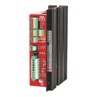
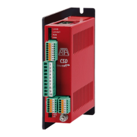
The R.T.A. ADW Series is a range of stepping motor drives designed for various industrial applications. These drives are characterized by their versatility, offering four selectable operation modes and various settings for motor speed control.
Function Description
The ADW Series drives are designed to control stepping motors, providing precise and reliable movement. They can operate in several modes, including:
- RUN Mode: The motor starts and stops based on an enable input, with a second input controlling direction.
- CW/CCW Mode: The motor runs either clockwise (CW) or counterclockwise (CCW) depending on the logic state of two inputs.
- START/STOP Mode: The motor starts only after a positive edge transition on a specific input and stops after a positive edge transition on another input. A third input sets the direction.
- LIMIT SWITCH Mode: This mode is suitable for applications requiring forward and backward movements controlled by two normally open limit switches at the ends of the course. AUTOSTOP functionality is always active in this mode.
Motor speed can be set either by an analog input, where speed is proportional to the analog input value (ANALOG MODE), or by pre-setting minimum and maximum speeds via dip-switches (DIGITAL MODE). The drives also feature an advanced microstepping function for smoother movement. An open collector STEP output provides a square wave signal with frequency proportional to the motor speed, with a fixed resolution of 800 steps/revolution.
Important Technical Specifications
The ADW Series includes models such as ADW 04, ADW 06, ADW 94, and ADW 96, with variations like ADW 04.V and ADW 06.V.
General Characteristics (Table 1):
| Characteristic |
ADW 04 / 04.V |
ADW 06 / 06.V |
ADW 94 |
ADW 96 |
| VDC nom (V) |
24 to 75 |
24 to 75 |
24 to 75 |
24 to 75 |
| INF min (A) |
0.65 |
1.9 |
0.65 |
1.9 |
| INF max (A) |
2 |
6 |
2 |
6 |
| Dimensions (mm) |
93.5 x 122 x 25 |
93.5 x 122 x 25 |
110 x 129.5 x 34 |
110 x 129.5 x 34 |
| Operating temperature |
+5°C to +40°C |
+5°C to +40°C |
+5°C to +40°C |
+5°C to +40°C |
Identification:
Models are identified as ADW ZX.Y, where:
- Z: 0 or 9 (open frame or boxed drive).
- X: 4 or 6 (low current or high current drive).
- .Y: Special version (if present, 'V' indicates screw input connector).
Power Supply:
- The drive requires a DC voltage supply (VDC nom) ranging from 24 to 75V.
- A capacitor of 10,000 µF with VDC ≥ 24 Volt and a capacitor of 2,700 µF with VDC ≥ 24 Volt are recommended for the power supply.
- The transformer power must be higher than the sum of the power requested by the drive and motor.
Current Settings:
Nominal phase current (INP) can be selected by the user among eight different values using DIP-SWITCHES. Automatic current reduction at motor standstill is 50% of the set value.
I/O Signals (Table 6):
| Pin |
RUN |
CW/CCW |
START-STOP |
LIMIT SWITCH |
Note |
| 1 |
Logic Input Common |
|
|
|
|
| 2 |
Current Off Input |
|
|
|
|
| 3 |
Direction Input |
Not used |
Direction Input |
Direction Input |
|
| 4 |
Oscillator Enable Input |
Enable Input CCW |
Start Input |
Limit Input CCW |
|
| 5 |
Not Used |
Enable Input CW |
Stop Input |
Limit Input CW |
|
| 6 |
High/Low Speed Input or Autostop |
Dip4 of DP2 enable AUTOSTOP |
|
|
|
| 7 |
Step Out (Open collector) |
|
|
|
|
| 8 |
Analog A-GND |
Referred to Analog A-GND |
|
|
|
| 9 |
Analog Input or Not used (Internal Ref.) |
Dip 3 of DIP2 enable/disable Analog Input |
|
|
|
| 10 |
+ 5 V |
|
|
|
|
Usage Features
Operation Modes and Settings:
- DIP-Switch DP2 (DIP 1, 2): Configures the operation mode (RUN, CW/CCW, START-STOP, LIMIT SWITCH).
- DIP-Switch DP2 (DIP 3): Activates or disables the analog input.
- DIP-Switch DP2 (DIP 4): Activates or disables AUTOSTOP.
- DIP-Switch DP1 (DIP 1, 2, 3): Sets the nominal current (INF).
- DIP-Switch DP1 (DIP 4, 5, 6): Sets the motor high speed.
- DIP-Switch DP1 (DIP 7, 8): Sets the motor low speed ratio.
- Jumpers/DIP (FC): Enables/disables automatic current reduction.
- Jumpers/DIP (CO): Forces ON/OFF the current off input.
- Jumpers/DIP (J3): Sets analog input range (0-5V or 0-10V).
- Jumpers/DIP (f/): Activates/deactivates division by 10 speed scale.
Analog Input:
- For analog mode, the speed is proportional to the analog input value (0-10V or 0-5V, selected via jumper J3).
- A potentiometer (MIN 5 KΩ) can be connected to pin 10 (+5V) for analog input control (jumper J3 must be ON).
LED Status Indicators:
- LED HV (green): ON indicates supply voltage within working range; OFF indicates no supply voltage or out of range.
- LED FAU (red): ON indicates the drive is in a non-working state due to thermal protection, max/min voltage, or short circuit/wrong motor connection. OFF indicates the drive is active.
- LED TER (yellow): ON indicates the drive is in a non-working state due to thermal protection. OFF indicates the drive is active.
Trimmer VL1:
Allows tuning the time constant of acceleration/deceleration ramp.
Maintenance Features
Protection and Alarms:
- The drive incorporates protection circuits for thermal protection, over/under voltage, and short circuits/wrong motor connections.
- All protection circuits and alarms reset automatically once the source of the alarm disappears.
- Memory must be reset by removing power supply voltage.
Environmental Conditions:
- Environment conditions class 3K3 (IEC 721-3-3): Operating temperature +5°C to +40°C, relative humidity 5% to 85% non-condensing.
- Pollution degree 2 (Use in Pollution degree 2 Environment): Installation in environments where only non-conductive pollution occurs, except for occasional temporary conductivity caused by condensation.
- Mechanical conditions class 3M1 (IEC 721-3-3): The equipment is designed for use in environments where it is not subject to conditions requiring special vibration or shock resistant casing.
Installation and Shielding:
- Shielded Motor Cable: Essential for reducing electromagnetic interference. The shield should be connected to the drive chassis and the motor frame.
- Power Supply Connections: Ensure proper grounding of the drive and motor to the earth potential.
- Transformer Selection: The power transformer should be adequately sized to account for both drive and motor losses.
- Cable Lengths: Keep shielded cables for power and motor connections between 5-6 meters. Signal cables should be kept separate from motor output cables.
- Vertical Mounting: KSM KIT BRACKET (open frame) or KSM01 DIN A KIT BRACKET (boxed drive) are available for vertical mounting, improving air flow and heat dissipation.
Compliance:
The device complies with the requirements of 2014/30/UE directive and EN61800-3 standard for electromagnetic compatibility.