PROGRAMMING THE XP-3
The XP-3 must be programmed to operate. All programming is done using RTI’s Integration Designer
®
software and is downloaded using the USB
Programming Port located on front of XP-3 or via Ethernet.
UPDATING FIRMWARE
It is highly recommended that this and all RTI products have the latest rmware installed. The rmware can be found in the Dealer section of the RTI
website (www.rticorp.com). Install the rmware using the USB Programming Port located on the front of XP-3.
Installation & Operation
MOUNTING
The XP-3 can be wall mounted (details below) or free standing.
The XP-3 does not need to be mounted near the equipment being controlled. The IR output ports and the optional Power Sensor modules can be
extended up to 1000 feet. If RS-232 control ports or the CM-232 Communication Module are used, the distance limitation is usually 50 feet depending
on baud rate.
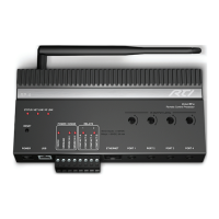
MOUNTING INSTRUCTIONS
To mount the XP-3 to a wall, shelf, or cabinet you must use
the enclosed mounting plate.
• Level and anchor XP-3 mounting plate to desired wall,
shelf, or cabinet by screwing appropriate wall, shelf, or
cabinet fasteners (not included with the XP-3) through
the mounting plate fastener holes.
• When mounting the XP-3, be certain to choose a safe
location (e.g. away from electrical junction boxes, circuit
breakers, wet locations, etc.)
• Afx the XP-3 to the mounting plate by placing the
XP-3 channel locks located on the rear of the XP-3 over
the XP-3 channel lock clips located on the front of the
mounting plate. Slide the XP-3 down until the channel
lock clips lock into place.
XP-3 Mounting Plate
Mounting Plate Fastner Holes
XP-3
Channel
Locks
Rear of XP-3
XP-3 Chan-
nel Lock
Clips
DB-9 Connector Pin Out
Pin Signal Signal
Name Description
1 DCD Carrier Detect
2 RXD Receive Data
3 TXD Transmit Data
4 DTR Data Terminal Ready
5 GND Signal Ground/Common
6 DSR Data Set Ready
7 RTS Request To Send
8 CTS Clear To Send
9 NC Not Connected
RJ-45 Connector Pin Out
Pin Signal Signal
Name Description
1 DSR Data Set Ready
2 DCD Carrier Detect
3 DTR Data Terminal Ready
4 GND Signal Ground/Common
5 RXD Receive Data
6 TXD Transmit Data
7 CTS Clear To Send
8 RTS Request To Send
RJ-45 TO DB-9 ADAPTER PINOUT
RS-232 PORT
The XP-3 is capable of two-way RS-232 communication and
uses industry standard cat5 cable with RJ-45 termination
(EAI-561). An RJ-45 to DB9 adapter is included with the XP-3.
NOTE: RS-232 communication is typically limited to 50 feet
depending on the baud rate.
ETHERNET
This RJ-45 port allows connection to a 10/100 Base-T Ethernet
network (LAN) for programming, control and two-way
communication with compatible devices. Network settings such
as the IP address are congurable within Integration Designer.
This port also supports Power-over-Ethernet (POE) which will
power the XP-3.
Ethernet
Network
(LAN)
XP-3
Channel
Locks
XP-3 Chan-
nel Lock
Clips
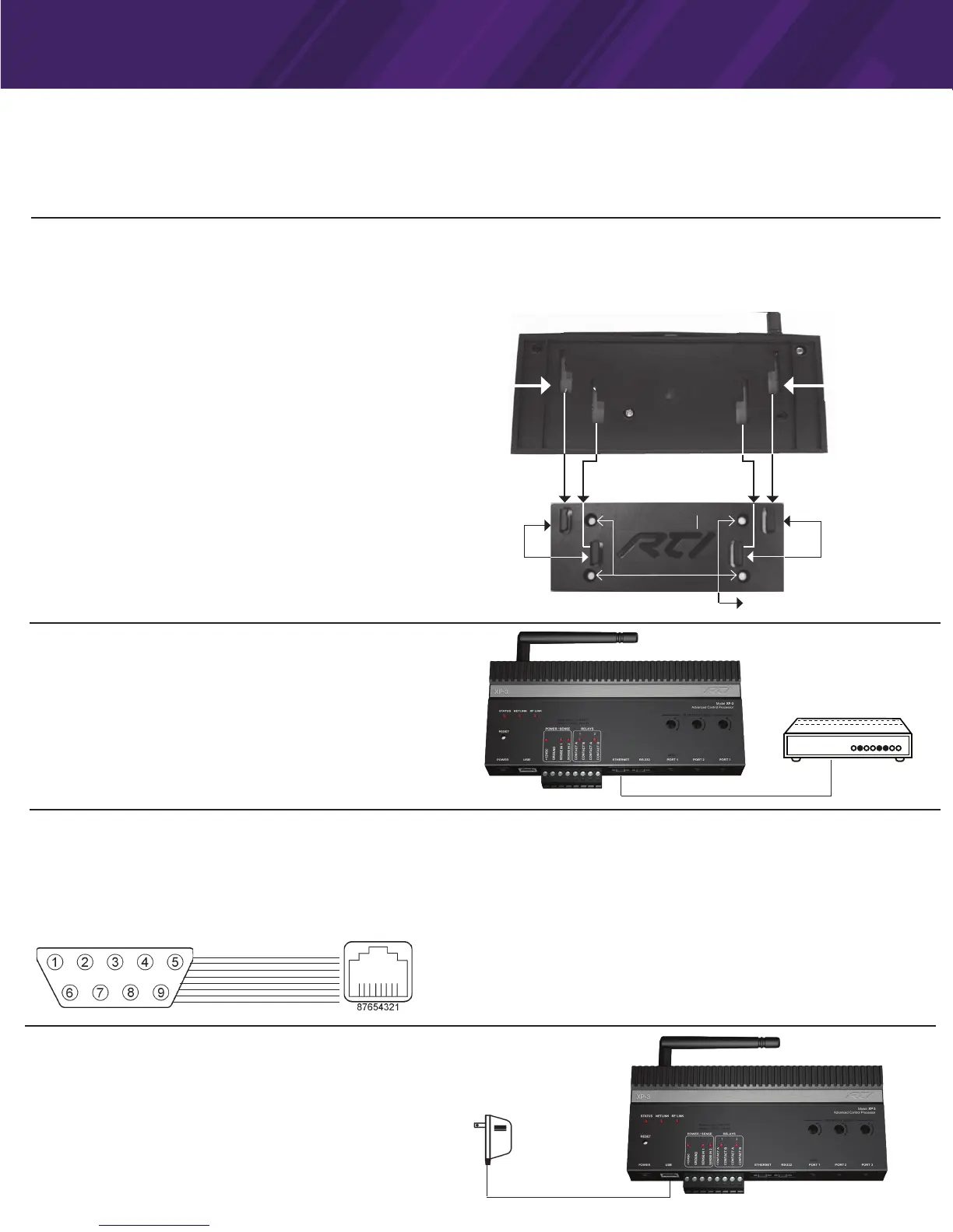
Power
Supply
POWER
To power the XP-3, use the supplied 12VDC/1Amp power supply.
ALTERNATIVE: POWER-OVER-ETHERNET (POE)
The XP-3 can alternatively be powered using Power Over Ethernet,
allowing the power to be extended to the XP-3 over the same Cat-5
cable that carries Ethernet communication. If this method will be
used, a class 3 POE router or POE injector will need to be used.
 Loading...