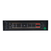
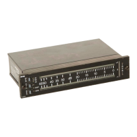
Gehäuse 10220 und Anschlusseinheit 11280
Case 10220 and bracket 11280
Über diese Anleitung Seite/Page iii
Scope of the manual Seite/Page iii
Inhaltsverzeichnis/Content
1. Einführung ................................................................................ 1-1
1.1. Beschreibung ...................................................................... 1-1
2. Inbetriebnahme und Anschlussbelegung .............................. 2-1
2.1. Inbetriebnahme ................................................................... 2-1
2.2. Anschlussbelegung ............................................................. 2-1
2.2.1. XLR-Anschlüsse .......................................................... 2-1
2.2.2. Sub-D-Remote-Buchse ............................................... 2-2
2.2.3. Schalterfunktionen ...................................................... 2-2
2.3. Geänderte Belegung und Funktionen mit Peakmeter ................
11528G ab Ser.-Nr. 1500 ....................................................... 2-3
2.3.1. Sub-D-Remote-Buchse ............................................... 2-3
2.3.2. Geänderte Schalterfunktionen ..................................... 2-4
3. Montage ................................................................................... 3-1
3.1. Aufbau ................................................................................ 3-1
3.2. Einbau der Instrumente .......................................................3-1
3.2.1. Einbau mit M3-Schrauben ........................................... 3-2
3.2.2. Einbau der Instrumente mit Klemmverriegelung ........... 3-3
3.3. Ausbau der Instrumente ...................................................... 3-4
3.3.1. Ausbau mit M3-Schrauben .......................................... 3-4
3.3.2. Ausbau der Instrumente mit Klemmverriegelung .......... 3-5
5. Introduction .............................................................................. 5-1
5.1. Description .......................................................................... 5-1
6. First time operation and connection ..................................... 6-1
6.1. First time operation .............................................................6-1
6.2. Digital audio connection ...................................................... 6-1
6.2.1. XLR sockets ............................................................... 6-1
6.2.2. Sub-D remote connector ............................................. 6-2
6.2.3. Switch functions.......................................................... 6-2
6.3. Changed assignment and function using PPM 11528G ............
(ser.-no. 1500 and above ....................................................... 6-3
6.3.1. Sub-D remote connector ............................................. 6-3
6.3.2. Changed switch functions ........................................... 6-4
7. Installation ............................................................................... 7-1
7.1. Mounting ............................................................................. 7-1
7.2. Installing the instruments .................................................... 7-1
7.2.1. Installation with M3 screws ......................................... 7-2
7.2.2. Mounting the instruments with clamping locks ............ 7-3
7.3. Removal of the instruments ................................................. 7-4
7.3.1. Dismounting with M3 screws....................................... 7-4
7.3.2. Dismounting the instruments with clamping locks ....... 7-5
 Loading...