MODEL 51240B/53540B/53640B/61240B/63540B/63640B
14
E. As the staining in liquid may cause impeller rotation not smooth, it
may affect the measurement accuracy of probe. Therefore, it shall
inspect and clean the impeller of probe periodically.
Figure1-3
b. As Figure 1-2, install a disc filter on the inlet of the filter.
c. Install valve A, valve B and valve C on the inlet, outlet and the middle of
the pipeline of inlet and outlet.
d. Glue the inlet of the system with the inlet of the valve with DN65 UPVC
pipeline (The outer diameter is φ75); Glue the flow meter with outlet of the
valve with DN65 UPVC pipeline (The outer diameter is φ75); Glue the
outlet of the system with flow meter with DN65 UPVC pipeline (The outer
diameter is φ75).
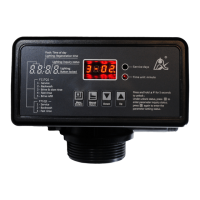
e. Disassemble the front cover of the valve, and connect the flow meter to
the flow meter connector of the main control board. (Refer P22 main
control board figure)
Notice:
● If making a soldered copper installation, do all sweat soldering before
connecting pipes to the valve. Torch heat will damage plastic parts.
● When turning threaded pipe fittings onto plastic fitting, use care not to
cross thread or broken valve.
● Inlet pipeline should be in parallel with outlet pipeline. Support inlet and
outlet pipeline with fixed holder.
● If the valve belongs to time clock type, there is no flow meter installation
 Loading...