Do you have a question about the Runxin F71B1 and is the answer not in the manual?
Covers advice for safe operation, handling, and environmental considerations.
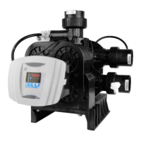
Details where the valve is used and its suitability for different systems.
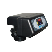
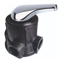
Highlights key features like sealing, manual function, and display.
Specifies the required working conditions for the filter valve.
Provides dimension information for product structure reference.
Instructions and warnings before proceeding with installation.
Guidelines for selecting an appropriate location for the unit.
Steps for connecting inlet, outlet, and drain pipelines.
Specific instructions for connecting the drain pipeline correctly.
Explains the indicators, buttons, and modes of the control board.
Details the functions, indicators, default settings, ranges, and instructions for parameters.
Illustrates how the working status is displayed on the control panel.
Visual representation of the filtration process flow.
Describes the main control board and its connection ports.
Explains the purpose of various connectors like signal output and interlock.
Details how to use signal output connectors for solenoid valves and pumps.
Covers interlock cables and liquid level controllers for pump operation.
Explains liquid level switch function and booster pump integration.
How to use interlock cables for parallel and series system configurations.
Explains how the pressure relief output prevents damage during rinsing.
Describes using external instruments like TDS meters or PLCs for control.
Lists tank sizes and filter material volumes for system setup.
Presents graphs showing pressure drop versus flow rate for different models.
Presents graphs showing pressure drop versus flow rate for different models.
Lists common problems, causes, and corrections for control valve issues.
Addresses issues related to the control board, display, and electrical service.
Exploded view and list of components for the F71B model valve body.
Detailed list of part numbers and quantities for the F71B valve body.
Exploded view of the F71G model valve body assembly.
Detailed list of part numbers and quantities for the F71G valve body.
Exploded view of the F67C model valve body assembly.
Detailed list of part numbers and quantities for the F67C valve body.
Exploded view of the F67G model valve body assembly.
Detailed list of part numbers and quantities for the F67G valve body.
Exploded view of the N75A model valve body assembly.
Detailed list of part numbers and quantities for the N75A valve body.
Exploded view of the N75B model valve body assembly.
Exploded view of the side-mounted connector body.
List of components for the side-mounted connector body.
| Riser Pipe | 1.05" OD |
|---|---|
| Output Voltage | 12V DC |
| Power | 6W |
| Protection | IP65 |
| Input Voltage | 100~240V/50~60Hz |