1. Opening Clearance
The opening in the wall or floor shall be larger than the damper/
sleeve assembly to permit installation or expansion. The opening
shall be a minimum of
1
/8" per foot (3 per 305) larger than the
overall size of the damper/sleeve assembly. The maximum open-
ing size shall not exceed
1
/8" per foot (3 per 305) plus 2" (51), nor
shall the opening be less than
1
/4" (6) larger than the damper/
sleeve assembly.
2.
Fasteners and Multiple Section Assembly
When joining multiple damper assemblies or fastening the damper
to the sleeve, dampers shall be fastened with 1/4-20 (M6) bolts,
number 10 (M5) screws, or
1
/2" (13) long welds staggered inter-
mittently on both sides. Space fasteners 6" (152) on center and a
maximum 2" (51) from the ends of the joining sections or from
each corner. When joining multiple damper assemblies, a continu-
ous
1
/8" (3) bead of Dow-Corning 700, silastic 732 RTV, or GE RTV
108 sealant shall be applied on the mullion joint. Press the
surface of the sealant in place to dispel any air. Another bead of
the same sealant shall be applied between the damper and
sleeve in the same manner. Only one side of the damper
requires caulking. Note the sealant is not required when dampers
are supplied for fire damper applications only and are not required
to be leakage rated. Multiple section high vertical mount dampers
include a 14 gauge x 5" (2 x 127) wide steel mullion plate
sandwiched between the damper frames where required. The
mullion plate must be the same material as the dampers.
3.
Damper Sleeve
Sleeve thickness must be equal to or thicker than the duct con-
nected to it. Sleeve gauge requirements are listed in the SMACNA
Fire, Smoke and Radiation Damper Installation Guide for HVAC
Systems and in NFPA90A. If a breakaway style duct/sleeve con-
nection is not used, the sleeve shall be a minimum of 16 gauge
(1.6) for dampers up to 36" (914) wide by 24" (610) high and 14
gauge (1.9) for dampers exceeding 36" (914) wide by 24" (610)
high. Damper sleeve shall not extend more than 6" (152) beyond
the fire wall or partition unless damper is equipped with an actua-
tor and/or factory installed access door. Sleeve may extend up to
16" (406) beyond the fire wall or partition on sides equipped with
actuator and/or factory installed access door. Sleeve shall termi-
nate at both sides of wall within dimensions shown.
4. Damper Orientation
Damper is designed to operate with blades running horizontally
and must be installed with
center line of damper frame
within the
wall or floor when they are in the closed position. Use "Mount With
Arrow Up" label as a guide for proper damper orientation. Hori-
zontal mount dampers must be installed with actuator above the
floor and temperature release device below the floor.
5.
Mounting Angles
Mounting angles shall be a minimum of 1
1
/2" x 1
1
/2" x 20 gauge
steel (38 x 38 x 1.0), installed on both sides of the partition and
attached only to the sleeve. Mounting angles must overlap the
partition a minimum of 1" (25). Do not weld or fasten angles
together at corners of dampers. Ruskin fire/smoke dampers may
be installed using Ruskin PFMA.
a. Mounting Angle Fasteners
Mounting angle fasteners shall be #10 (M5) bolts or screws,
#10 self-tapping concrete anchors or concrete screws,
1
/2" (13)
long tack welds or
3
/16" (3) diameter steel rivets.
b. Mounting Angle Fastener Spacing
Fasteners shall be spaced at 8" (203) o.c. with a minimum of 2
fasteners on each side, top and bottom.
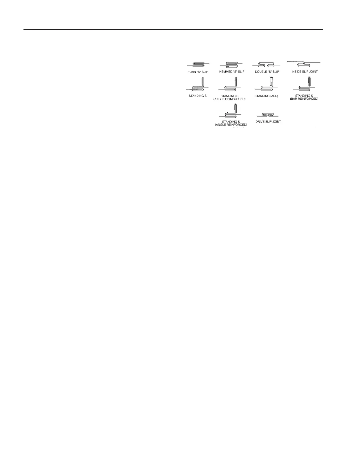
6. Duct/Sleeve Connections
a. Break-away Duct/Sleeve Connections
Rectangular ducts must use one or more of the connections
depicted below:
A maximum of two #10 (M5) sheet metal screws on each side
and the bottom, located in the center of the slip pocket and
penetrating both sides of the slip pocket may be used.
Connections using these slip joints on the top and bottom with
flat drive slips up to 20" (508) long on the sides may also be
used.
b. Round and Oval Break-away Connections
Round and flat oval break-away connections must use either
a 4" (102) wide drawband or #10 (M5) sheet metal screws
spaced equally around the circumference of the duct as fol-
lows:
• Duct diameters 22" (559) and smaller – maximum 3
screws.
• Duct diameters over 22" (559) and including 36" (914) –
maximum 5 screws.
• Duct diameters over 36" (914) and up to and including 191"
(4851) total perimeter – maximum 8 screws.
For flat oval ducts, the diameter is considered the largest
(major) dimension of the duct. These connections are de -
picted in the SMACNA Fire, Smoke, and Radiation Damper
Installation Guide.
Note: When optional sealing of these joints is desired, the
following sealants may be applied in accordance with the
sealant manufacturer's instructions:
Design Polymerics – DP 1010 Precision – PA2084T
Hardcast, Inc. – Iron Grip 601 Eco Duct Seal 44-52
c. Flanged Break-away Style Duct/Sleeve Connections.
Flanged connection systems manufactured by Ductmate,
Nexus or Ward are approved break-away when installed as
shown on the Flanged Systems Breakaway Connections
Supplement.
TDC and TDF roll-formed flanged connections using
3
/8" (10)
steel bolts and nuts, and metal cleats, as tested by SMACNA,
are approved break-away connections when installed as
shown on the Flanged Systems Breakaway Connections
Supplement.
d. Non-Break-away Duct/Sleeve Connections
If other duct/sleeve connections are used, the sleeve shall be
a minimum of 16 gauge (1.6) for dampers up to 36" (914)
wide x 24" (610) high and 14 gauge (2.0) for dampers
36" (914) wide x 24" (610) high.
7. Actuator Connections
Electric and pneumatic actuators are to be connected in accor-
dance with wiring and piping diagrams developed in compliance
with applicable codes, ordinances and regulations.
8. Installation and Maintenance
The damper must be installed so it is square and free from rack-
ing. Do not compress or stretch the damper frame into the duct or
opening. Lift or handle the damper using sleeve or frame. Do not
lift damper using blades or actuators. Each fire/smoke damper
should be examined on a regular basis to ensure it is not rusted or
blocked. In addition, each damper should be tested periodically,
(NFPA recommends annually or semiannually, depending on the
application) to ensure it will perform as intended. Care should be
exercised to ensure that such tests are performed safely and do
not cause system damage.
ALL STATED SPECIFICATIONS ARE SUBJECT TO CHANGE WITHOUT NOTICE OR OBLIGATION.
II-FSD60-3-0121/ Replaces II-FSD60-3-316
© Ruskin January 2021


 To Next Page
 Loading...