EasyManua.ls Logo

Russound A-BUS A-KP2 User Manual

Russound A-BUS A-KP2
2 pages
To Next Page IconTo Next Page
Page #1 background imageLoading...
Page #1 background image
12 34
IR E
MITTERS
IR
C
ONFIRM
DESIGNED IN USA MADE IN KOREA
P
OWER
24VDC 2.5A
S
TATUS
12VDC 100mA
N
EWMARKET
, NH U.S.A.
A
UDIO
O
UT
L R
A
UDIO
I
N
L R
3
12
4
L
INK
OUT
IN
K
EYPAD
O
UTPUTS
4-ZONE, 1-SOURCE
SURFACE MOUNT AUDIO HUB
A-H4
R+ R- L- L+ R+ R-
LINE OUT
L- L+
SPEAKER OUT
LINE INPUT
SENSING
SPEAKER A OUT
12V
TRIG
INPUT
12V TRIG
OUT 100mA
STEREO
VIDEO
INPUT
SENSING
DELAY
BRGD *
MONO
GAIN
SPEAKER B OUT
LR
1
2
3
4
5
AC
120V
60Hz
1.5A~
AMPLIFIED INPUT
SENSING
DEFAULT
AMPLIFIED INPUT
AVIS : RISQUE DE CHOC
ELECTRIQUE – NES PAS
OUVRIR.
* FOR BRIDGED OPERATION
SEE MANUAL
L
R
WARNING : SHOCK
HAZARD – DO NOT OPEN
12345678
O
N
O
FF
VO
L
SO
URCE SELECT
ALL OFF
SOURCE
CONTROL
M
UTE
LAST
SLEEP
INFO
MENU
INPUT
EN
TER
12
3
4
56
7
8
9
0
GUIDE
EXIT
SELECT
PWR
S
E
T
U
P
VOL CH
1
2
3
4
CBL
VCR
TV
1
23
4
CONNECTION DIAGRAMS FOR RUSSOUND
®
MODEL A-KP2. REFER TO THE INSTRUCTIONS ON BACK. DIAGRAMS ARE NOT TO SCALE.
A-KP2 REAR
A-LRC1
A-KP2 Front
On/Off
Volume Up/Down
IR Window
IR Confirmation &
Status LED
Left & Right
Volume Trim
STATUS Disabled
STATUS Enabled
Underside of A-KP2
J-Box
Decora®
faceplate
A-KP2
Negative (–)
Positive (+)
When wiring directly to Amplified Keypad,
use T568A RJ45 wire configuration
110 punchdown
connectors
on A-KP2
RJ45 Wall Plate
(optional) located
near Hub
RJ45 CAT-5 patch cable
A-BUS
®
Hub or A-BUS
®
Ready receiver
Speakers (8 Ohm)
Multi-Source
Switch (Single-
Source is default)
Functions in Multi-
Source Mode:
On/Off
All Off
Source Select
CAT-5
(behind wall)
Wire order
BROWN
GREEN
ORANGE
BLUE
Multi-Source
Single-Source
1
1
1
2
2
3
8
4
4 3
5
6
7
GREEN
ORANGE
BLUE
ORANGE
BROWN
External Amplifier (optional)
to speakers
Question and Answer IconNeed help?

Do you have a question about the Russound A-BUS A-KP2 and is the answer not in the manual?

Russound A-BUS A-KP2 Specifications

Power IconPower
power requirements+24VDC, 750mA
status input requirements+12VDC, 20mA
power supply unit24VDC/2.5A
Connections IconConnections
cat-5 connection110 Punchdown
maximum cat-5 cable length250 feet
rj45 wire configurationT568A

Summary

Installation and Connection Notes

Installation Notes

Provides essential preliminary checks before connecting the A-KP2 to the A-BUS® system.

CAT-5 Connections

Details the use of CAT-5 cables for connecting the A-KP2 to A-BUS® Hubs or receivers.

Status Indicator

Explains the function and configuration of the STATUS jumper and LED on the A-KP2.

Speaker Connections

Guides on connecting one pair of 8 Ohm speakers to the A-KP2's output terminals.

External Amplifier Connection

Describes how to connect an external amplifier to the A-KP2's LINE OUT for increased power.

Volume Trim Adjustments

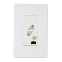
Details the use of rotary potentiometers for setting maximum volume and L/R balance.

Mounting Instructions

Provides guidance on testing the system and installing the A-KP2 into a standard J-Box.

Keypad Operation

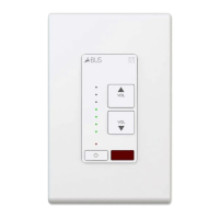
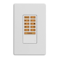
Explains how to control power, volume, and source selection using the A-KP2 or optional remote.

Multi-Source Mode Switch

Instructs on setting the switch for Single-Source or Multi-Source A-BUS® hubs.

A-BUS System Overview

A-BUS® System Description

Introduces the A-BUS® system as a multi-room audio solution using CAT-5 wiring.

System Components

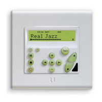
Outlines the three main areas of an A-BUS® system: Control Modules, Hubs, and Power Supply.

A-KP2 Product Details

A-KP2 Overview

Describes the A-KP2 as an in-wall amplified keypad for A-BUS® systems.

A-KP2 Features

Lists the key features of the A-KP2 amplified keypad module.

A-KP2 Specifications

Provides technical specifications for the A-KP2, including impedance and dimensions.

Warranty Information

Limited Warranty

Details the two-year warranty for the A-KP2 and conditions for service and repair.

Related product manuals