EasyManua.ls Logo

Ryobi EXPAND-IT RYEDG12VNM - User Manual

Ryobi EXPAND-IT RYEDG12VNM
136 pages
Print Icon
To Next Page IconTo Next Page
Loading...
OPERATOR’S MANUAL
MANUEL D’UTILISATION
MANUAL DEL OPERADOR
EDGER ATTACHMENT
ACCESSOIRE COUPE-BORDURES
ACCESORIO PARA RECORTAR BORDES
RYEDG12/RYEDG12VNM
WARNING: To reduce the
risk of injury, the user must read and
understand the operator’s manual
before using this product.
TABLE OF CONTENTS
General Safety Rules ..........................2
Specific Safety Rules ..........................3
Symbols ..............................................4
Features ..............................................5
Assembly ........................................ 5-6
Operation ........................................ 6-7
Maintenance .......................................8
Parts Ordering/Service ........ Back Page
AVERTISSEMENT : Pour
réduire les risques de blessures,
l’utilisateur doit lire et veiller à bien
comprendre le manuel d’utilisation
avant d’employer ce produit.
TABLE DES MATIÈRES
Règles de sécurité générales .............. 2
Règles de sécurité particulières .......... 3
Symboles ............................................4
Caractéristiques ..................................5
Assemblage .................................... 5-6
Utilisation ........................................ 6-7
Entretien .......................................... 7-8
Commande de pièces /
réparation .......................... Páge arrière
ADVERTENCIA: Para reducir
el riesgo de lesiones, el usuario debe
leer y comprender el manual del
operador antes de usar este producto.
ÍNDICE DE CONTENIDO
Reglas de seguridad generales ..........2
Reglas de seguridad específicas ........3
Símbolos .............................................4
Características ....................................5
Armado ........................................... 5-6
Funcionamiento .............................. 6-7
Mantenimiento ................................ 7-8
Pedidos de piezas/
servicio ........................... Pág. posterior
SAVE THIS MANUAL FOR
FUTURE REFERENCE
CONSERVER CE MANUEL
POUR FUTURE RÉFÉRENCE
GUARDE ESTE MANUAL
PARA FUTURAS CONSULTAS

Table of Contents

Question and Answer IconNeed help?

Do you have a question about the Ryobi EXPAND-IT RYEDG12VNM and is the answer not in the manual?

Overview

This document describes three different attachments for a power head: an Edger Attachment (RYEDG12/RYEDG12VNM), a Jet Fan Blower Attachment (RYAXA22/RYAXA22VN/RYAXA22VNM), and a Pruner Attachment (RYPRN33/RYPRN33VN/RYPRN33VNM), as well as a Cultivator Attachment (RYTIL66/RYTIL66VN/RYTIL66VNM).

Edger Attachment (RYEDG12/RYEDG12VNM)

Function Description:

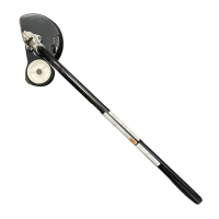
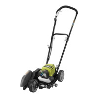
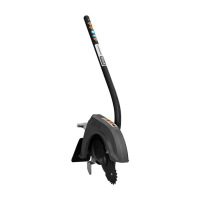
The Edger Attachment is designed for edging along sidewalks, driveways, flower beds, and similar areas. It is not intended for any other purpose. The attachment connects to a power head via a coupler device.

Important Technical Specifications:

  • Blade Length: 8 in.
  • Edging Depth: Adjustable from 1/2 in. to 2-1/2 in.
  • Replacement Blade Model Number: AC04215

Usage Features:

  • Assembly: The edger attachment requires assembly. Ensure all parts are present and undamaged before assembly. The attachment shaft connects to the power head by aligning a button on the attachment with a guide recess on the power head coupler and sliding the shafts together until the button locks into a positioning hole. The knob on the coupler must be securely tightened before operation.
  • Operation: Always hold the unit with both hands, with the right hand on the rear handle and the left hand on the front handle, at approximately hip height. Operate at full throttle when used with a gas power head to prevent oil dripping from the muffler.
  • Adjusting Depth of Cut: Stop the engine/motor and remove the spark plug wire/disconnect power before adjusting. Loosen the adjusting knob and move the wheel arm up to increase depth or down to decrease depth. Tighten the knob securely after adjustment. Initially, adjust the blade depth from 1/2 in. to 1 in. deep and make shallow cuts to test.
  • Operating Tips: Use the arrow guide on the blade guard for alignment. Cut at a steady pace; if the blade bogs down, slow your pace. Light contact with hard surfaces is acceptable. For best results, edge when grass is dry to prevent clogging and uneven edges. If the blade guard clogs, stop the unit and clear debris.
  • Safety: Always wear eye and hearing protection, heavy long pants, boots, and gloves. Secure long hair. Keep bystanders at least 50 ft. away. Do not operate in poor lighting or overreach. Inspect the unit for loose/damaged parts before each use. Never touch hot surfaces around the muffler or cylinder of a gas power head. Stop the engine/motor and disconnect power before making adjustments or repairs.

Maintenance Features:

  • General Maintenance: Avoid using solvents on plastic parts. Use clean cloths to remove dirt, dust, oil, and grease.
  • Replacing the Blade: Stop the engine/motor and disconnect power. Align the slot in the flange washer and gear case with the slot in the flange, then insert the holding pin. Use a 3/4 in. (19 mm) socket wrench to loosen the blade nut clockwise. Remove the old blade, clean debris, and center the new blade flat on the flange washer. Install the cupped washer with the hole off the blade surface. Install the blade nut and tighten counterclockwise to 11 ft. lbs. Ensure the blade is correctly installed and securely fastened before each use.
  • Attaching the Storage Hanger: The hanger cap can be pushed onto the attachment shaft until the button locks. A secondary hole on the shaft can also be used for hanging.
  • Storing the Attachment: Store indoors in a dry, well-ventilated, child-inaccessible place, away from corrosive agents.

Jet Fan Blower Attachment (RYAXA22/RYAXA22VN/RYAXA22VNM)

Function Description:

The Jet Fan Blower Attachment is designed for clearing leaves and other debris from lawns, decks, and driveways. It is intended for blower use only and not for vacuum use. The attachment connects to a power head via a coupler device.

Important Technical Specifications:

  • Blowing Performance (at Nozzle Outlet):
    • MPH (peak velocity): 140
    • MPH (average velocity): 120
    • CFM: 475
    • Measured at the blower tube outlet per ANSI B175.2 standard for measuring blower performance with a RYOBI 2 Cycle Power Head.

Usage Features:

  • Assembly: The blower attachment requires assembly. Ensure all parts are present and undamaged. The attachment shaft connects to the power head by aligning a button on the attachment with a guide recess on the power head coupler and sliding the shafts together until the button locks into a positioning hole. The knob on the coupler must be securely tightened before operation.
  • Operation: Always hold the unit with both hands, with the right hand on the rear handle and the left hand on the front handle, at approximately hip height. Carry the unit slightly above ground level to prevent wear.
  • Operating Tips: Operate in compliance with all applicable laws. Blow around the outer edges of debris piles, not directly into the center. A simple blast can clear debris from difficult-to-reach areas. Ground-level air blast is ideal for most sweeping jobs.
  • Gas Power Head Usage: Start the engine and let it warm up to get accustomed to blower operation. Air force increases as engine speed increases to full throttle. Full power is not always necessary, especially in tight quarters, to avoid turbulence and floating dust.
  • Safety: Always wear eye and hearing protection, heavy long pants, boots, and gloves. Secure long hair. Keep bystanders at least 50 ft. away. Do not operate in poor lighting or overreach. Inspect the unit for loose/damaged parts before each use. Never touch hot surfaces around the muffler or cylinder of a gas power head. Stop the engine/motor and disconnect power before making adjustments or repairs. Do not run without the air outlet and all guards in place. Never direct the air outlet towards people, animals, plants, or delicate objects. Keep the air inlet clear of debris. Never place the blower on any surface other than hard, clean when running.

Maintenance Features:

  • General Maintenance: Avoid using solvents on plastic parts. Use clean cloths to remove dirt, dust, oil, and grease.
  • Attaching the Storage Hanger: The hanger cap can be pushed onto the attachment shaft until the button locks. A secondary hole on the shaft can also be used for hanging.
  • Storing the Attachment: Clean and lubricate thoroughly before storing. Store indoors in a dry, well-ventilated, child-inaccessible place, away from corrosive agents.

Pruner Attachment (RYPRN33/RYPRN33VN/RYPRN33VNM)

Function Description:

The Pruner Attachment is designed for trimming small branches and limbs up to 6 inches in diameter, including limbing and pruning. It connects to a power head or an extension shaft via a coupler device.

Important Technical Specifications:

  • Bar Length: 10 in.
  • Replacement Chain Pitch: .375 in.
  • Replacement Chain Type: Low Profile (Skip Tooth)
  • Replacement Chain Drive Links: 40
  • Replacement Bar Part Number: 671834008
  • Replacement Chain Part Number: 690583003

Usage Features:

  • Assembly: The pruner attachment requires assembly. Ensure all parts are present and undamaged. The attachment shaft connects to the power head or extension shaft by aligning a button on the attachment with a guide recess on the power head coupler and sliding the shafts together until the button locks into a positioning hole. The knob on the coupler must be securely tightened before operation.
  • Installing Shoulder Strap and Strap Hanger: A shoulder strap is required for support. If the power head does not have a strap hanger, install the provided hanger by pulling it apart and placing it over the power head shaft, near the upper knob. Secure it with a bolt and lock nut. Attach the shoulder strap clip to the hanger and adjust its position for hip-level support.
  • Preparation for Cutting: Wear non-slip gloves. Maintain a firm grip with both hands on the handles. Keep your body to the left of the chain line. Never stand directly under the limb being cut.
  • Basic Cutting Procedure:
    1. Fully squeeze the trigger and allow the engine/motor to reach full speed before entering the cut. Maintain full speed throughout the cut.
    2. Make a shallow first cut (1/4 of limb diameter) on the underside of the limb close to the main limb or trunk.
    3. Make a second cut from the top side of the limb outboard from the first cut.
    4. Make a final cut close to the trunk. For second and final cuts, hold the front cutting guide against the limb for stability. Allow the chain to cut; exert only light downward pressure.
    5. Release the trigger as soon as the cut is complete.
  • Limbing and Pruning: Plan cuts carefully, considering the direction of fall. Remove long branches in several stages, starting with lower branches. Work slowly, maintaining firm grip, secure footing, and balance. Keep the tree between you and the chain. Do not cut from a ladder or unstable support. Do not make flush cuts until the limb's weight is reduced. Do not use for felling or bucking.
  • Position for Starting: Lay the pruner on the ground, ensuring no objects or obstructions are near the bar and chain.
  • Safety: Always wear eye, hearing, and head protection, heavy long pants, boots, and gloves. Secure long hair. Keep bystanders at least 50 ft. away. Do not operate in poor lighting or overreach. Inspect the unit for loose/damaged parts before each use. Never cut near electric cords or lines. If the blade jams on an electrical line, do not touch the blade; disconnect power immediately. Stop the engine/motor and disconnect power before making adjustments or repairs. Never touch hot surfaces. Be aware of kickback.

Maintenance Features:

  • General Maintenance: Avoid using solvents on plastic parts. Use clean cloths to remove dirt, dust, oil, and grease.
  • Replacing the Bar and Chain: Stop the engine/motor and disconnect power. Remove the bar nut and drivecase cover. Place the bar onto the bar stud, ensuring the chain tensioning pin fits into its hole. Fit the chain over the sprocket and into the bar groove, with cutters facing the bar tip. Replace the drivecase cover and reinstall the bar nut, finger-tight only. Remove slack by turning the chain tensioning screw clockwise. Lift the bar tip to check for sag; release and turn the screw 1/2 turn clockwise until no sag exists. Hold the tip up and tighten the bar nut securely. Chain is correctly tensioned when snug but turnable by hand without binding.
  • Power Head Idle Speed Adjustment (Gas Power Heads Only): If the chain turns at idle, adjust the idle speed screw counterclockwise to reduce RPM and stop chain movement. Consult the power head manual.
  • Chain Tension: Check tension frequently. A cold chain is correctly tensioned when snug but turnable without slack. Re-tension when drive links hang out of the bar groove. Warm chains will have drive links hanging approximately .050 in. (1.25 mm) out of the groove. New chains stretch and require frequent tension checks.
  • Chain Oiler: Use Premium Bar and Chain Lubricant. Remove the cap, pour 8 oz. into the tank, and tighten the cap securely. Refill the tank every hour for electric power heads or every time the engine is fueled for gas power heads. Do not use dirty or contaminated lubricants.
  • Chain Maintenance: The chain is very sharp; wear protective gloves. Sharpen when wood chips are small/powdery, the chain must be forced, or it cuts to one side. Improper filing angles can increase kickback. Depth gauge setting affects cutting ability and kickback risk. If cutter teeth hit hard objects, have a service dealer sharpen the chain.
  • How to Sharpen the Cutters: Tighten chain tension so it doesn't wobble. File at the mid-point of the bar. Wear gloves. Use a 5/32 in. round file and holder. Keep the file level with the top plate of the tooth. Stroke towards the front corner with light but firm pressure, lifting on return. File all left-hand cutters in one direction, then all right-hand cutters in the opposite direction. Remove filings with a wire brush. Dull or improperly sharpened chains can cause excessive engine/motor speed and damage.
  • Attaching the Storage Hanger: The hanger cap can be pushed onto the attachment shaft until the button locks. A secondary hole on the shaft can also be used for hanging.
  • Storing the Attachment: Clean and lubricate thoroughly before storing. Store indoors in a dry, well-ventilated, child-inaccessible place, away from corrosive agents. Always place the scabbard on the cutting blade before storing.

Cultivator Attachment (RYTIL66/RYTIL66VN/RYTIL66VNM)

Function Description:

The Cultivator Attachment is designed for breaking up garden soil to prepare seed beds for planting and for shallow cultivating to remove weeds. It connects to a power head via a coupler device.

Important Technical Specifications:

  • Tine Size: 8 in.
  • Tilling Depth: 7-3/4 in.
  • Tilling Width: 7-10 in.

Usage Features:

  • Assembly: The cultivator attachment requires assembly. Ensure all parts are present and undamaged.
    • Installing the Tines: Install tines before connecting to the power head. The cultivator has four tines (two inner labeled B and C, two outer labeled A and D). Tines must be installed in the correct orientation: tine C on the left of the gearbox (stamped side away from gearbox), tine B on the right (stamped side away from gearbox). Place felt washers on each side of the tine shaft against the inner tines. Place outer tine D on the left (stamped side in toward tine C), and outer tine A on the right (stamped side in toward tine B). The angled edge of the tine blades should face the ground. Secure tines with hitch pins. If tines are installed incorrectly, the unit will not operate properly. Wear heavy gloves when installing/removing/adjusting tines as they can become sharper with wear.
    • Joining to Power Head: The cultivator attachment connects to the power head by aligning a button on the attachment with a guide recess on the power head coupler and sliding the shafts together until the button locks into a positioning hole. The knob on the coupler must be securely tightened before operation.
    • Attaching the J-Handle: The J-handle provides a barrier to maintain a safe distance from rotating tines. If the power head lacks a handle, install the provided J-handle. Place the bottom clamp on the drive shaft, insert the tab of the top clamp into the slot, and insert the J-handle end between the clamps so holes align and the handle is to the operator's left. Push the bolt through, install a flat washer and wing nut, and tighten securely. Adjust the handle position as indicated by the label on the drive shaft.
  • Operation: Hold the cultivator with both hands, with the right hand on the rear handle and the left hand on the front handle. Maintain a firm grip. For most soil types, partial throttle is sufficient to avoid shortening engine/drivetrain life.
  • Operating the Cultivator: Move the cultivator to the work area before starting. Start the engine/motor on flat, level ground. Hold handles firmly, depress the trigger to moderate speed, then lower the cultivator to contact the ground. Pull the cultivator carefully toward you while it digs into the soil to reduce effort.
  • Safety: Always wear eye and hearing protection, heavy long pants, boots, and gloves. Secure long hair. Keep bystanders at least 50 ft. away. Do not operate in poor lighting or overreach. Inspect the unit for loose/damaged parts before each use. Never use near underground electric cables, telephone lines, pipes, or hoses. Rotating tines can cause severe injury; keep body parts away. Use extreme caution when reversing or pulling the machine. Stop the engine/motor if abnormal vibration or noise occurs. Keep fasteners tight. Check hitch pins are fully inserted. Stop the engine/motor when leaving the cultivator or making repairs. Ensure all guards are properly attached. Be careful when tilling hard ground as tines can propel the cultivator forward. Do not overload the machine by tilling too deep or too fast. After extended use, the gearbox may become hot; do not touch until it cools.

Maintenance Features:

  • General Maintenance: Avoid using solvents on plastic parts. Use clean cloths to remove dirt, dust, oil, and grease.
  • Tine Maintenance: Occasionally apply lubricant to the shaft to keep tines free. If tines are worn, replace all four tines as a set.
  • Regular Tine Pattern: The factory-set regular tine pattern is best for most applications. Pay attention to the hub position relative to the tines.
  • Narrow Tine Pattern: For confined areas, remove hitch pins, left and right outer tines (A and D), and felt washers. Reinstall hitch pins in alternate holes. Do not force tines; apply penetrating lubricant if needed. Clean and lubricate shaft and tine hubs when reinstalling.
  • Stony or Rocky Soil Tine Pattern: For stony soil, remove hitch pins, tines, and felt washers. Reinstall tines B and C on opposite sides (B on left, C on right when facing attachment). Reinstall felt washers. Reinstall tines A and D (D and B on one side, A and C on the other). Replace hitch pins. This pattern creates a wider center gap and requires additional passes.
  • Attaching the Storage Hanger: The hanger cap can be pushed onto the attachment shaft until the button locks. A secondary hole on the shaft can also be used for hanging.
  • Storing the Attachment: Store indoors in a dry, well-ventilated, child-inaccessible place, away from corrosive agents.

Ryobi EXPAND-IT RYEDG12VNM Specifications

General IconGeneral
BrandRyobi
ModelEXPAND-IT RYEDG12VNM
CategoryEdger
LanguageEnglish

Related product manuals