1
English
GB
FR DE ES IT NL PT DK SE FI NO RU PL CZ HU RO LV LT EE HR SI SK GR TR
SPECIAL SAFETY RULES
■ Wear ear protectors. Exposure to noise can cause
hearing loss.
■ Use auxiliary handle(s), if supplied with the tool.
Loss of control can cause personal injury.
■ Hold power tool by insulated gripping surfaces,
when performing an operation where the cutting
accessory may contact hidden wiring. Cutting
accessory contacting a «live» wire may make exposed
metal parts of the power tool «live» and could give the
operator an electric shock.
ASSEMBLY
AUXILIARY HANDLE ASSEMBLY
See Figure 2.
An auxiliary handle is packed with the drill for ease of
operation and to help prevent loss of control. The handle
can be mounted on the opposite side for left or right hand
use.
■ Insert handle screw into hole located above trigger
switch and seat hex head into hole.
■ Slide handle collar onto screw, seat hex end of collar
into hex hole. Hex hole for depth stop rod should be
on top of collar.
■ Slide depth stop rod into hex shaped hole on top of
collar.
■ Slide depth guide clamp into notch in collar. Clamp
holds depth rod firmly in place.
NOTE: When properly installed, the teeth on the depth
stop rod should be aligned with the teeth indicator on the
depth stop rod clamp.
■ Thread auxiliary handle onto screw and secure tightly.
NOTE: Be sure the auxiliary handle is securely tightened
against the depth stop rod clamp. This secures the depth
stop rod at the desired depth of cut. It also secures the
auxiliary handle.
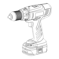
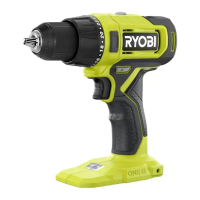
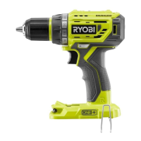
DESCRIPTION
1. Keyless chuck
2. Torque adjustment ring
3. Quick mode selector
4. Two-speed gear train
5 . Rotation selector (forward/reverse/center lock)
6. Depth rod stop
7. Bit storage
8. Switch trigger
9. Mag Tray™
10. Handle screw
11. Hex head hole
12. Handle coller
13. Teeth
14. Depth stop rod clamp
15. Auxiliary handle
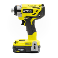
16. Battery pack (Not included)
17. Latches
18. Depress latches to release battery pack
19. Reverse
20. Forward
21. Chuck jaws
22. Lock (tighten)
23. Unlock (release)
24. Low speed
25. High speed
26. Drive mode
27. Drill mode
28. Hammer mode
29. To increase torque
30. To decrease torque
31. Bit
32. Screws
33. Bit holder
34. Drilling depth
35. Drill bit
36. Scale
37. To increase drilling depth
38. To loosen
39. To tighten
40. To decrease drilling depth
41. Chuck sleeve
SPECIFICATIONS
Voltage 18 V
Chuck 2-13 mm
Switch Variable speed
No load speed (Drill mode):
-Lo speed 0-400 min
-1
-Hi speed 0-1500 min
-1
Hammer speed (Blows per minute):
-Lo speed 0-5200 min
-1
-Hi speed 0-19500 min
-1
Max. torque 49 Nm
Weight (not incl. battery pack) 1.68 Kg
LCDI1802
BPL-1820
BPL-1815
BCL-1800
BCS618
BCL1418
BPP-1815
BPP-1815M
BPP-1817
BPP-1817M
BC-1815S
BC-1800
BCL-1800
BCS618
BCL1418
BCL14181H
BCL14183H
BCL14181H
BCL14183H
MODEL
BATTERY
PACK
(not included)
COMPATIBLE
CHARGER
(not included)
 Loading...