1
3
1
2
4
10
8
9
5
15
11
12
13
14
16
6
7
20
18
19
17
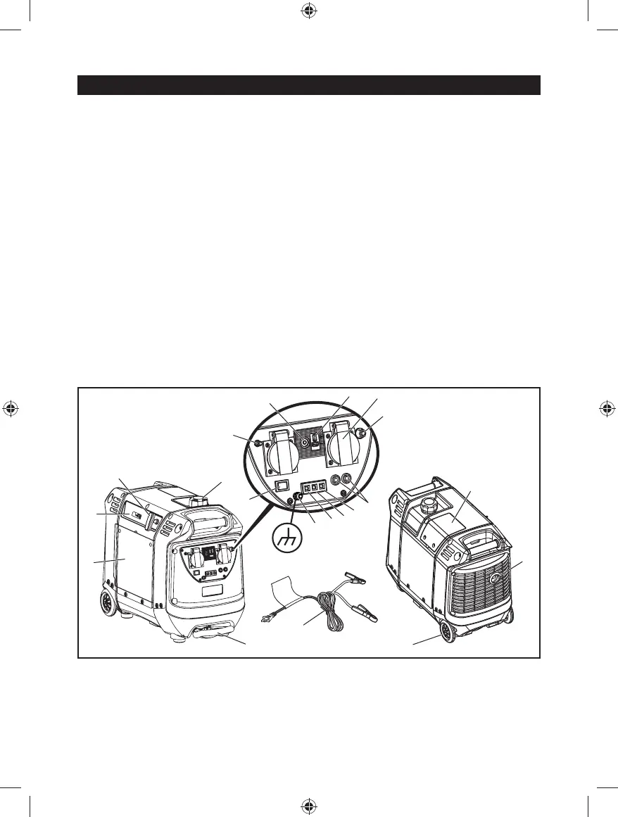
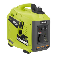
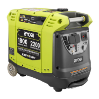
Fig. 1
1. Engine cover
2. Engine/choke lever/on-off switch/fuel valve lever
3. Starter grip and rope
4. Fuel cap
5. Parallel kit terminal
6. 10 Amp, AC circuit breaker
7. 240 Volt AC, 15 Amp receptacles
8. DC circuit breaker
9. 12 Volt DC receptacle
10. Auto idle switch
11. Power indicator
12. Overload indicator
13. Low oil indicator
14. Reset button
15. Ground terminal
16. Retractable handle
17. Battery charging cable
18. Spark plug cover
19. Muffl er with spark arrestor screen
20. Wheel
21. Funnel
22. Oil cap/dipstick
23. Off
24. On
25. Engine/choke lever in off position
26. Cold start position
27. Run position
28. Battery
29. Screw
30. Washer
31. Air fi lter cover
32. Filter element, large
33. Filter element, small
34. Container
35. Spark plug cap
36. Spark plug
37. Carburetor drain screw
DESCRIPTION