7 — English
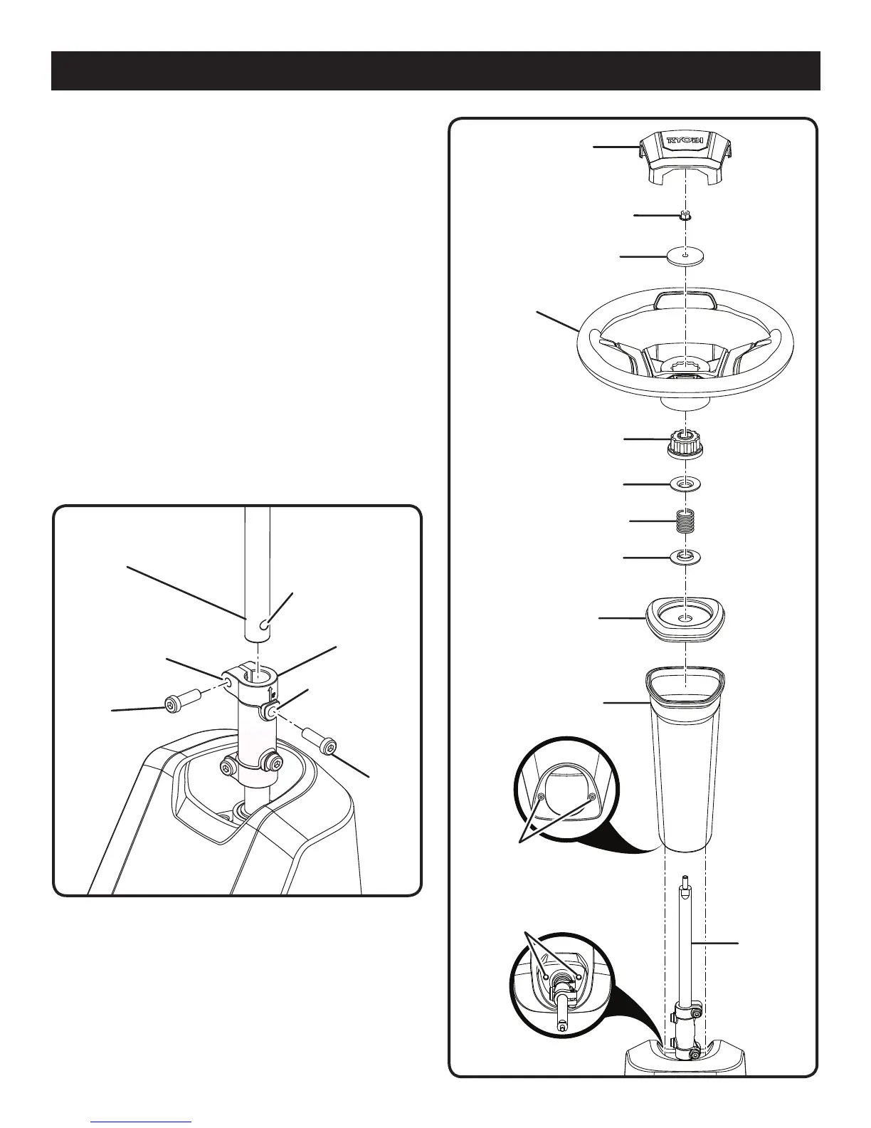
STEERING WHEEL
STEERING WHEEL
COVER
ASSEMBLY
Fig. 4
SHAFT
STEERING COLUMN
UPPER
STEERING SHAFT
COUPLER
BOLT
ASSEMBLE THE STEERING COLUMN
See Figures 3 - 4.
Install the upper steering shaft into the coupler, rotating
as needed to align hole in shaft with bolt hole in coupler.
Install two bolts and tighten securely. Torque to 6 ft.lbs.
Insert steering column over shaft. Note the tabs on the
bottom of the steering column that fit into the holes in
the opening and make sure steering column is securely
seated.
Install the steering column cover so that it is seated se-
curely. The upper steering shaft will protrude through the
opening in the cover.
Install the flange washer (flange up), the spring, the second
flange washer (flange down), and the steering wheel hub
onto the upper steering shaft.
Make sure the mower’s wheels are pointed straight ahead,
then install the steering wheel over the wheel hub.
Install the flat washer and flange nut; tighten securely.
Torque nut to 6 ft. lbs.
Install the steering wheel cover.
FLAT WASHER
FLANGE NUT
STEERING WHEEL HUB
SPRING
FLANGE WASHER
(POINTED DOWN)
STEERING COLUMN
COVER
FLANGE WASHER
(POINTED UP)
TABS
HOLES
Fig. 3
BOLT
HOLE IN
SHAFT
UPPER
COUPLER
BOLT HOLE
BOLT HOLE
IN COUPLER

 Loading...