2. TERMINAL DESCRIPTION
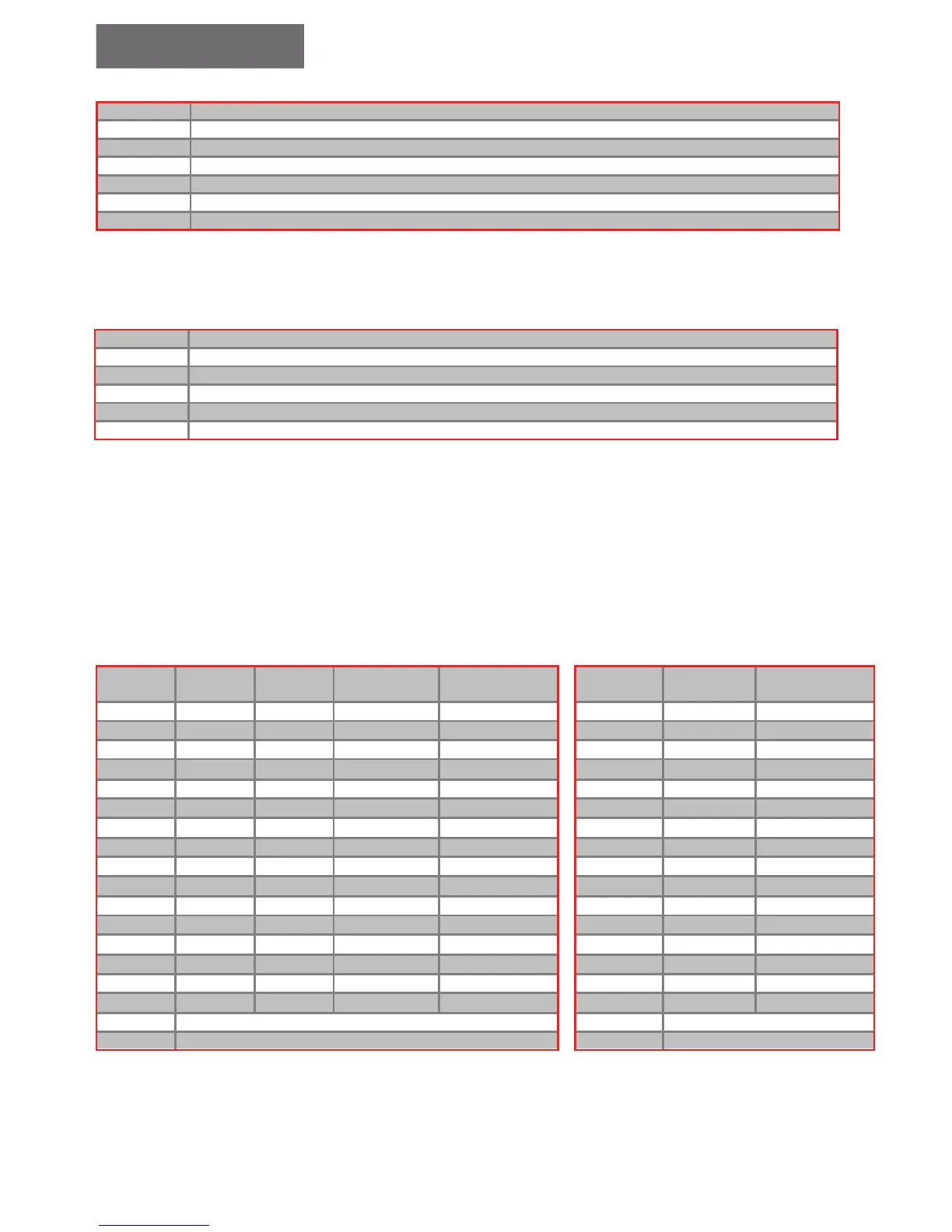
2.3.4 INDICATOR OUTPUT TERMINALS
2.3.4 INDICATOR OUTPUT TERMINALS
↑ Up direcon arrow
↓ Down direcon arrow
A Floor informaon A for Gray code indicator
B Floor informaon B for Gray code indicator
C Floor informaon C for Gray code indicator
D Floor informaon D for Gray code indicator
E Floor informaon E for Gray code indicator
Note that when no extension is installed, D output becomes Down arrow (active positive) and E output
becomes Up arrow (active positive).
2.4 INCREMENTAL ENCODER TERMINALS
2.4 INCREMENTAL ENCODER TERMINALS
GND Negave supply
ENC
VCC Posive supply
ENC
A- Phase A inverted
ENC
A+ Phase A
ENC
B- Phase B inverted
ENC
B+ Phase B
Incremental encoder with dierential output shall be used.
The internal supply is 5VDC. However, a dierential output encoder working on an external up to 12VDC
supply would work. Note that the encoder must be powered from one source only (either external or
internal with dip switch #4 ON).
2.5 CALL TERMINALS
2.5.1 CALL TERMINALS LOCATED ON BOARD
2.5.1 CALL TERMINALS LOCATED ON BOARD
The allocation of calls on call terminals depends on whether one or more extension boards are present.
The table below shows how the calls are allocated:
Without
Extension
Down
Collecve
Full
Collecve
Mul
Collecve
MulF
Collecve
With 1
Extension
Down
Collecve
Full Collecve
CT
15 Down 7 Down 5 Car+Down 15 Down8
CT
15 Car 15 Up 4
CT
14 Down 6 Down 4 Car+Down14 Down7
CT
14 Car 14 Up 3
CT
13 Down 5 Down 3 Car+Down13 Down6
CT
13 Car 13 Up 2
CT
12 Down 4 Down 2 Car+Down 12 Down5
CT
12 Car 12 Up 1
CT
11 Down 3 Down 1 Car+Down 11 Down4
CT
11 Car 11 Up 0
CT
10 Down 2 Up 4 Car+Down 10 Down3
CT
10 Car 10 Car 10
CT
9 Down 1 Up 3 Car+Down 9 Down2
CT
9 Car 9 Car 9
CT
8 Down 0 Up 2 Car+Down 8 Car8+Down1
CT
8 Car 8 Car 8
CT
7 Car 7 Up 1 Car+Down 7 Car7+Up7
CT
7 Car 7 Car 7
CT
6 Car 6 Up 0 Car+Down 6 Car6+Up6
CT
6 Car 6 Car 6
CT
5 Car 5 Car 5 Car+Down 5 Car5+Up5
CT
5 Car 5 Car 5
CT
4 Car 4 Car 4 Car+Down 4 Car4+Up4
CT
4 Car 4 Car 4
CT
3 Car 3 Car 3 Car+Down 3 Car3+Up3
CT
3 Car 3 Car 3
CT
2 Car 2 Car 2 Car+Down 2 Car2+Up2
CT
2 Car 2 Car 2
CT
0 Car 0 Car 0 Car+Down 0 Car0+Up0
CT
0 Car 0 Car 0
17
V
~ Board power supply – 17v~ b
17
V
~ Board power supply – 17v~ b
17
V
~ Board power supply – 17v~ b
17
V
~ Board power supply – 17v~ b
Down calls starting at ground oor level and below are internally converted to up calls. The position of the ground oor is determined by setting the number of basements; refer to
section 5. For instance if there are no basements, then the ground oor is on the rst level and consequently Down 0 call will be internally interpreted as an Up 0 call.
Multiplexing mode cannot be used in group mode.
 Loading...