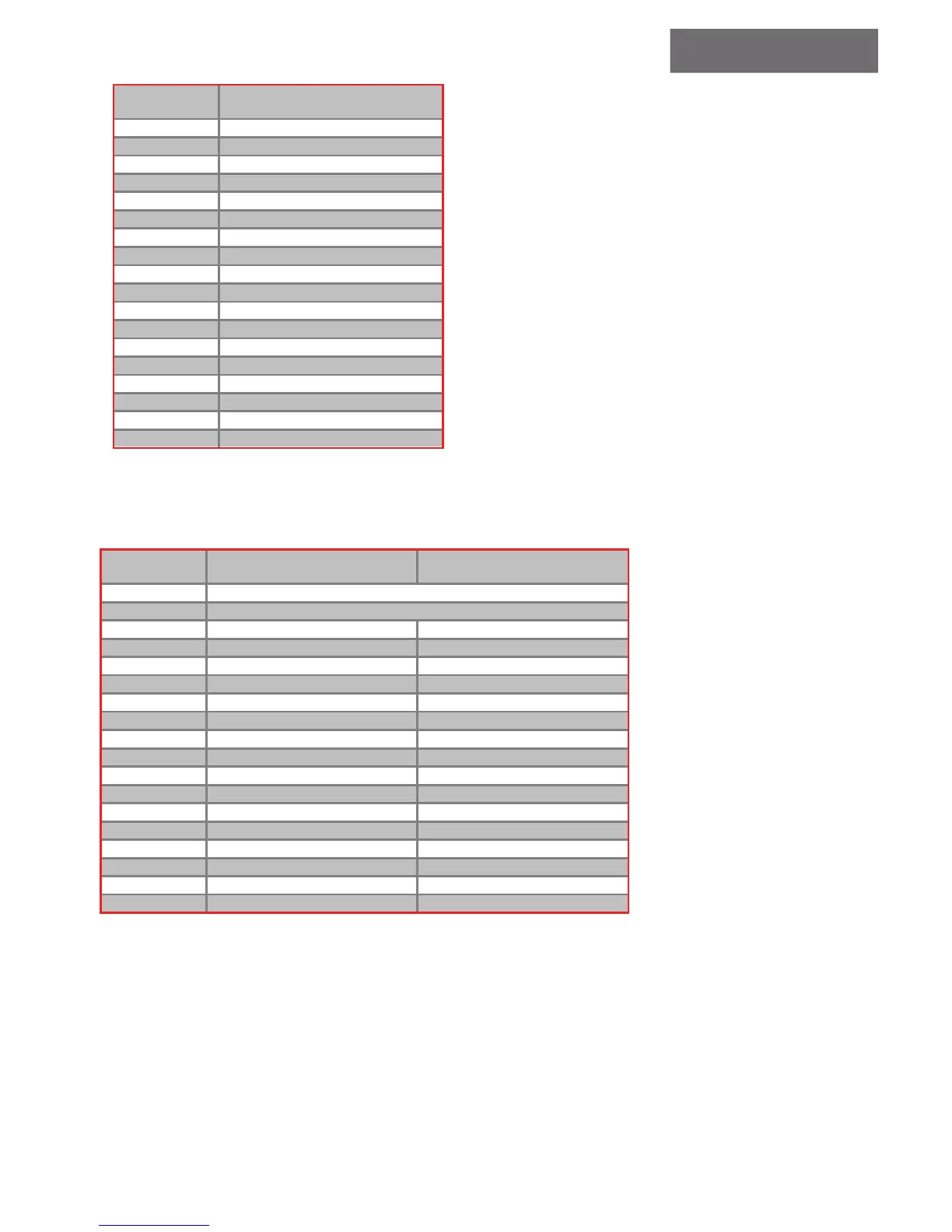
2. TERMINAL DESCRIPTION
With 2 or 3
Extensions
Down Collecveor
Full Collecve
CT
15 Car 15
CT
14 Car 14
CT
13 Car 13
CT
12 Car 12
CT
11 Car 11
CT
10 Car 10
CT
9 Car 9
CT
8 Car 8
CT
7 Car 7
CT
6 Car 6
CT
5 Car 5
CT
4 Car 4
CT
3 Car 3
CT
2 Car 2
CT
1 Car 1
CT
0 Car 0
17
V
~ Board power supply – 17v~a
17
V
~ Board power supply – 17v~b
2.5 CALL TERMINALS ON EXTENSION BOARDS
2.5 CALL TERMINALS ON EXTENSION BOARDS
If more than one extension board is required, the boards should be cascaded. The table below shows how
the calls are allocated on the extension board #1:
With 1
Extension
Down Collecve Full Collecve
P
+22
V
Biasing voltage from periphery supply – posive side
GND
Biasing voltage from periphery supply – negative side
EC
0 Down 0 Up 5
EC
1 Down 1 Up 6
EC
2 Down 2 Up 7
EC
3 Down 3 Up 8
EC
4 Down 4 Up 9
EC
5 Down 5 Down 1
EC
6 Down 6 Down 2
EC
7 Down 7 Down 3
EC
8 Down 8 Down 4
EC
9 Down 9 Down 5
EC
10 Down 10 Down 6
EC
11 Down 11 Down 7
EC
12 Down 12 Down 8
EC
13 Down 13 Down 9
EC
14 Down 14 Down 10
EC
15 Down 15 -
Down calls starting at ground oor level and below are internally converted to up calls. The position of the ground oor is determined by setting the number of basements;
refer to section 5. For instance if there are no basements, then the ground oor is on the rst level and consequently Down 0 call will be internally interpreted as an Up 0 call.
Although this is not a call, it is listed with the calls for convenience.
 Loading...