S-LIGHTING
S-3 www.slservice.pl 8
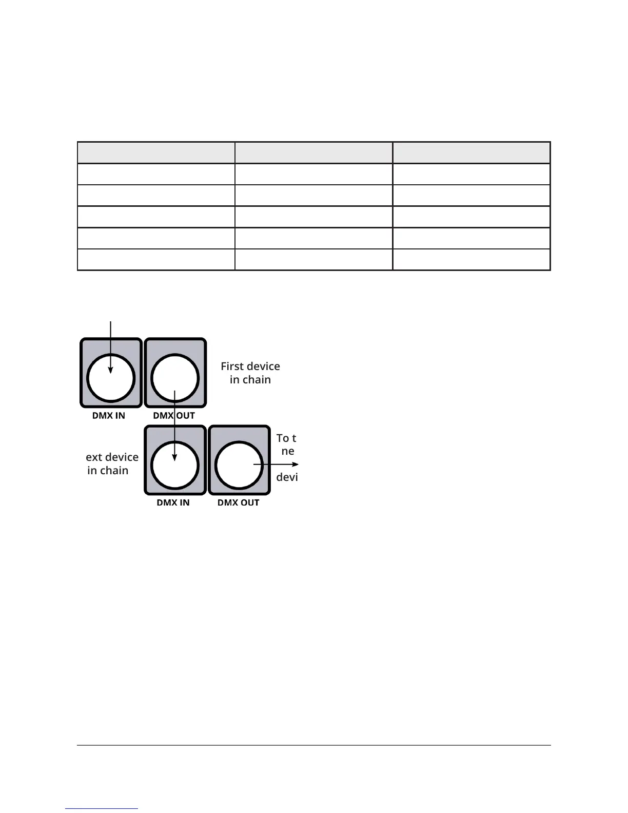
First device
in chain
Signal IN
To the
next
device
Next device
in chain
Step 1: Connect the male
connector of the DMX cable
to the female connector (output)
on the controller.
Step 2: Connect the female
connector of the DMX cable
to the rst device’s male
connector (input).
Note: It doesn’t matter which device address
is the rst one connected. We recommend
connecting the device in terms of their proximi-
ty to the controller, rather than connecting
the lowest device number rst, and so on.
Setting up DMX control
Step 3: Connect other devices in the chain from output to input
as above. Place a DMX terminator on the output of the nal device
to ensure the best communication.
Fixture linking (Master/Slave Mode)
1. Connect the (male) 3-pin connector side of the DMX cable to the
output (female) 3-pin connector of the rst device.
2. Connect the end of the cable coming from the rst device, which
will have a (female) 3-pin connector to the input connector of the
next device consisting of a (male) 3-pin connector. Then, proceed
to connect from the output as stated above, to the input
of the following device (and so on).
3-Pin / 5-Pin
If you use a controller with a 5 pin DMX output connector, you will
need to use a 5 pin to 3 pin adapter. They are widely available over
the Internet and from specialty retailers, but if you’d like to build
your own, the table below details a proper cable conversion:
Conductor 3-Pin female (Output) 5-Pin male (Input)
Ground/Shield Pin 1 Pin 1
DMX Data (-) Pin 2 Pin 2
DMX Data (+) Pin 3 Pin 3
Not used. no connector Pin 4
Not used. no connector Pin 5