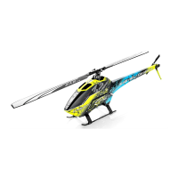
Do you have a question about the SAB Heli Division GOBLIN KRAKEN 580 and is the answer not in the manual?
| Brand | SAB Heli Division |
|---|---|
| Model | GOBLIN KRAKEN 580 |
| Main Blades | 580mm |
| Skill Level | Advanced |
| Assembly Required | Yes |
| Type | RC Helicopter |
| Battery | 6S LiPo |
| Motor | Not included |
| ESC | Not included |
| Servos | Not included |
Details on finding your serial number and registering your kit online for updates and support.
Highlights that the helicopter is dangerous, complex, requires careful assembly, and proper handling.
Advises flying in designated areas, knowing radio systems, and being aware of blade dangers.
States SAB Heli Division's limited liability for damages and user acceptance of risks.
Outlines the warranty terms, limitations, and purchaser remedies for defects.
Lists essential external components like motor, ESC, batteries, servos, and radio system.
Lists necessary tools, threadlockers, lubricants, and adhesives for the assembly process.
Provides general assembly advice, symbol explanations, and thread locker usage.
Details the items included within the main product box for assembly.
Provides a specific note regarding the CA glue application for the carbon rod assembly.
Confirms the transmission unit is assembled and ready for use, with a reference to page 40.
Informs about the compatibility and availability of standard size servos not included in the kit.
Guides on positioning linkage balls and aligning servo arms before installation in the model.
Offers a recommendation for routing servo wires for optimal setup.
Details the assembly process for the right side of the main helicopter frame.
Details the assembly process for the left side of the main helicopter frame.
Provides instructions for assembling the battery guide component.
Explains how to adjust battery tray play using the eccentric bushing.
Shows the assembled frame group and transmission group, with a note on screw installation.
Advises against installing a specific screw at the current stage of assembly.
Illustrates the assembled frame group and transmission, with a note on screw installation.
Advises not to install a specific screw at this time.
Details the assembly of the uniball radius arms for the helicopter head.
Provides instructions for assembling the radius arms of the helicopter head.
Guides on assembling the center hub component of the helicopter head.
Details the assembly of the linkage rods for the head mechanism.
Explains different O-ring setups for sport, 3D, and hard 3D flight styles.
Advises on checking preload, adding shims, and replacing O-rings after flight cycles.
Shows the assembled head components like uniball radius arms and linkage rods.
Guides on assembling the swashplate with uniballs and reference pin.
Recommends using Microlube GL261 grease for specific assembly points.
Details the assembly of linkage rods, specifying initial length for servo to swash plate connections.
Guides on assembling the tail blade grips, including bearings and spacers.
Details the assembly of the tail pitch slider mechanism.
Provides notes regarding left/right side assembly and bearing ID selection.
Illustrates the assembly of the tail rotor components, including pulley and side plate.
Guides on assembling the bell crank lever for the tail mechanism.
Shows the installation of the tail fin and the tail belt component.
Details the process of attaching the boom block support to the tail boom using bolts and nuts.
Explains how to secure the nut block to the boom using CA glue and tightening bolts.
Shows the assembled boom group and locking element for the tail.
Guides on assembling the tail servo, including arm, uniball, and block.
Illustrates the assembled tail boom with the servo installed.
Provides guidance on installing tail servo wires using zip ties.
Advises waiting for glue cure and ensuring smooth tail push rod movement.
Explains how to adjust preload on the carbon rod if it's too tight.
Lists available reduction ratios and provides configuration examples with battery, motor, ESC, and pulley.
Recommends maximum safe RPMs for motor operation, with specific limits for blade lengths.
Specifies the maximum and minimum shaft heights for motor installation.
Instructs on using internal or external holes on pulleys based on tooth count.
Details the procedure for setting the motor belt tension correctly.
Provides a tip on using a specific tool to set the motor belt tension.
Shows how to mount the ESC and notes the possibility of using zip ties for securing.
Illustrates a wiring solution, recommends hot glue for connections, and using servo extensions.
Advises checking battery position for CG and securing them with tape and straps.
Emphasizes ensuring the battery tray locking pin is engaged for safety before flying.
Guides on installing canopy grommets and quick knobs, and confirming security.
Suggests using a small drop of CA glue on grommets to secure canopy mounts.
Lists essential pre-flight checks including radio setup, wiring, gear ratio, and blade security.
Covers collective/cyclic pitch, blade tracking adjustments, and canopy security.
Explains different O-ring and damper setups for tuning the head's response.
Recommends tail pulley changes and larger tail blades for low RPM flying.
Explains different O-ring and damper setups for tuning the head's response.
Recommends tail pulley changes and larger tail blades for low RPM flying.
Advises checking parts frequently, lubricating linkages, and performing general inspections after flights.
Recommends replacing nylon screws after any crash, even a soft one.
Ensures main and tail rotor dampening is consistent and main blades are securely tightened.
Verifies tightness of main hub screws, power connectors, tail group screws, and linkages.
Confirms correct tension of tail and motor belts, and tightness of tail pulley set screws.
Checks for vertical main shaft play, FBL-RX connector integrity, and proper lubrication of key parts.
Confirms the transmission module is assembled and provides a note on heat for loctite neutralization.
Details the steps for removing and replacing the main shaft, including screw tightening.