R
Robert MoyerAug 4, 2025
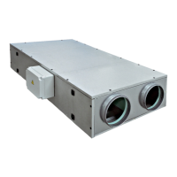
Why is there insufficient air flow and pressure in my Sabiana Energy Plus Heating System?
- AAshley MartinAug 4, 2025
If the Sabiana Heating System's air flow is insufficient, and the pressure is low, it could be due to several reasons: * The ducted system and/or extraction points might be clogged, requiring cleaning of both the system and the intake point. * Frost may have formed on the exchanger; consider assessing the use of a preheating coil. * Pressure drops may have been underestimated; double-check the operating point on the recovery unit's graph. * The rotation speed might be insufficient; check and recalibrate the fans' operating voltage. * The filter could be dirty; clean or replace the filter media, always using original filter media to maintain the unit's efficiency. * The heat exchanger might be clogged; clean the mouth of the heat exchanger.