Do you have a question about the Sabiana Carisma Whisper CFF and is the answer not in the manual?
Explains warning symbols and icons used in the manual.
Identifies the intended audience for the manual.
Lists crucial safety instructions and general warnings.
Details safety measures implemented in the unit's design and use.
Outlines essential safety precautions before performing any work on the unit.
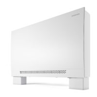
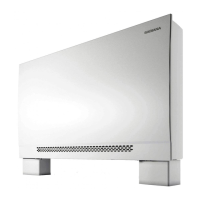
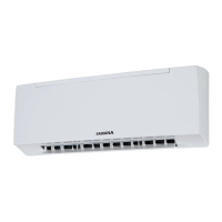
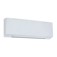
Provides a general description of the fan coil's purpose and application.
Details the primary components of the fan coil unit.
Lists key technical data, operating limits, and performance characteristics.
Specifies the water flow rate limits for different coil configurations.
Provides instructions for receiving, moving, and storing the unit safely.
Guides on mechanical installation placement and air intake considerations.
Specifies required clearance distances around the unit for installation.
Details dimensions and guidance for drilling mounting holes in walls.
Presents dimensional data for various fan coil models.
Illustrates the procedure for mounting the unit on a wall.
Continues to show details for wall mounting the fan coil unit.
Advises on duct connections and adjusting air discharge direction.
Provides instructions for connecting water pipes and pressure limits.
Details the installation requirements for the condensate drain pipe.
References technical data for relevant valves used with the unit.
Highlights essential safety warnings for electrical connections.
Specifies the required voltage, frequency, and connection points.
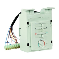
Step-by-step guide for installing the UP-ECO power unit for CB-E control.
Instructions for connecting the electrical motor of the fan coil unit.
Details the correct procedure for connecting the grounding cable.
Step-by-step guide for installing the UP-Touch power unit.
Instructions for connecting the electrical motor for CB-Touch control.
Details the correct procedure for connecting the grounding cable for CB-Touch.
Explains the configuration options using dip switches on the control board.
Describes the functionality of the auxiliary relays (BO/CH contacts).
Directs users to specific manuals for control unit usage.
Provides instructions for cleaning and replacing the air filter.
Details the steps required to safely remove the air filter.
Outlines the procedure for correctly re-installing the air filter.
Instructions for checking and cleaning the unit's coils.
Lists the annual maintenance tasks recommended for the unit.
Guidance on environmentally responsible disposal of the product.
Explains symbols, abbreviations, and connections in wiring diagrams.
Illustrates the standard electrical connections for power and controls.
Shows the wiring specific to the CB-E power unit and remote control.
Shows the wiring for the CB-Touch power unit and its control interface.
Details the connectors and layout of the Up-Touch electronic board.
Explains symbols and connections specific to CB-Touch controls.
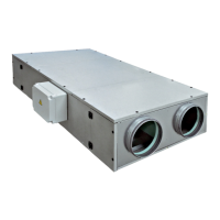
Presents detailed dimensions for the MV and IV versions of the unit.
Illustrates the hydraulic connections for MV and IV versions.
Specifies the dimensions of the unit when packaged for transport.
Lists the weight and water capacity of the unit for different models.
Shows diagrams and pressure drop curves for 3-way valves.
Shows diagrams and pressure drop curves for 2-way valves.
Details the dimensions and installation of floor mounting feet.
Presents detailed performance data including air flow, power consumption, and sound levels.
Manufacturer's official declaration of compliance with EU directives.
| Voltage | 230 V |
|---|---|
| Frequency | 50 Hz |
| Insulation Class | Class I |
| IP Rating | IP20 |
| Type | Fan Coil Unit |
| Installation | Wall Mounted, Ceiling Mounted |
| Dimensions (L x W x H) | Varies by model |
| Weight | Varies by model |